
74121 IC Description TTL Monostable Multivibrator IC

The 74L121 and 74L122 are both monostable multivibrator ICs designed for generating precise timing pulses. The 74L121 is a single monostable multivibrator that produces a single output pulse in response to a trigger input. The output pulse width is determined by external components, specifically a timing capacitor (Cext) and a resistor (Rext). The operation of the 74L121 allows for the generation of a one-shot pulse that can be used in various timing applications.
In contrast, the 74L122 is a retriggerable monostable multivibrator that can extend the duration of the output pulse if triggered again before the pulse has completed. This feature is particularly useful in applications requiring adjustable timing intervals. The clear function allows for immediate resetting of the output state, providing additional control over the timing sequence.
For accurate and repeatable pulse widths, it is recommended to connect an external resistor between Rext/Cext and the positive supply voltage (Vcc), while leaving the internal resistor (Rint) unconnected. This configuration ensures that the timing circuit operates within its intended specifications. When variable pulse widths are desired, a variable resistor can be connected between Rint or Rext/Cext and Vcc, allowing for real-time adjustments to the pulse duration.
The timing characteristics of these ICs are illustrated in timing charts, which provide essential information for designers to understand the relationship between the input trigger and the output pulse duration. The first timing chart is relevant for both the 74L121 and 74L122, while the second chart specifically pertains to the 74L121, detailing its unique timing parameters. For further clarification and detailed visual representations, enlarged versions of these charts, along with additional timing capacitor information for the 74122, are available through the provided link. This comprehensive understanding of the 74L121 and 74L122 ICs enables engineers to effectively implement these components in various electronic applications requiring precise timing control.The 74L121 and 74L122 ICs pin out diagram works any any style 74xx121 or 74xx122 DIP chip, but the timing graphs are only valid for the TTL families indicated. The 74121 shown above provides a single Monostable Multivibrator function. While the 74122 shown below provides a retriggerable Monostable Multivibrator function with clear. A Monostable M ultivibrator is also called a One Shot. An external timing capacitor may be connected between Cext and Rext/Cext. For accurate repeatable pulse widths connect an external resistor between Rext/Cext and Vcc leaving Rint open [unconnected]. To obtain variable pulse widths connect a variable resistance between Rint or Rext/Cext and Vcc. The first chart works for either the 74L121 or 74L122; however, the second chart only applies to the 74L121.
Use this link 74121 / 74122 Pulse Width Charts to find enlarged versions of the two charts above and an external timing capacitor chart for the 74122. 🔗 External reference
Related Circuits
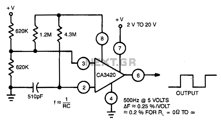
This multivibrator utilizes a CA3420 BiMOS operational amplifier to enhance frequency stability. The output frequency remains largely unaffected by supply voltage variations. Due to the inherent buffering action of pin 6, the frequency shift is approximately 0.2% when the...

Message in a Bottle is an Arduino microcontroller and sensor project that enables an individual to record their voice inside a glass bottle and send it to someone else for playback. By uncorking the bottle and speaking into it,...
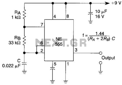
An astable multivibrator based on the 555 timer is presented. The frequency is approximately 975 Hz, determined by the values of RB and C. The astable multivibrator configuration using the 555 timer is a popular circuit for generating square wave...

A multivibrator is an electronic circuit that implements various simple two-state systems, such as oscillators, timers, and flip-flops. The most common type is the astable multivibrator, which continuously oscillates between two states, generating a square wave. Another type is...
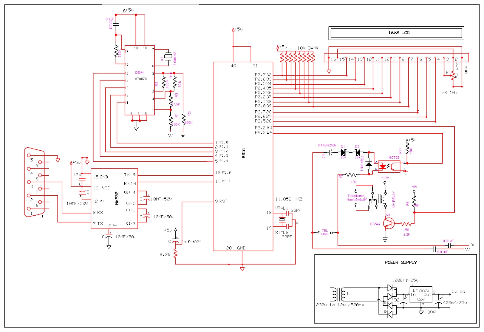
An Interactive Voice Response (IVR) system is a communication system that enables automated telephone call access to specific computer database information. This technology allows a computer to detect DTMF (Dual-tone multi-frequency) keypad inputs and generate voice responses based on...
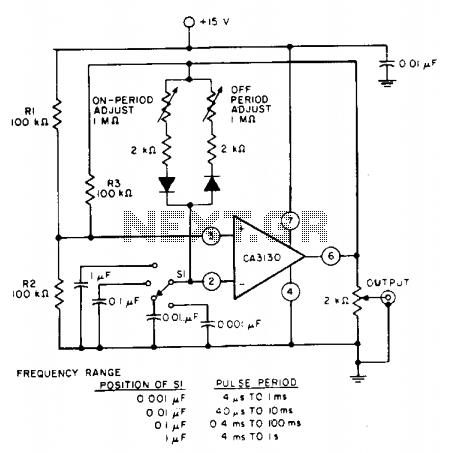
The pulse repetition rate is determined by adjusting switch SI to the desired position, and this rate remains relatively constant even when the resistors that control the on-period and off-period are modified. Resistors R1 and R2 set the biasing...