
Multivibrator

A multivibrator circuit is an essential component in electronic design, providing functionality for a wide range of applications. The astable multivibrator operates without any stable states, continuously toggling between high and low outputs. This oscillation is characterized by a square wave signal, which can be utilized in clock generation, signal modulation, and timing applications. The configuration typically includes two NPN or PNP transistors, feedback resistors, and capacitors that establish the timing characteristics of the oscillation. The frequency of oscillation can be adjusted by varying the resistor and capacitor values, making it versatile for different applications.
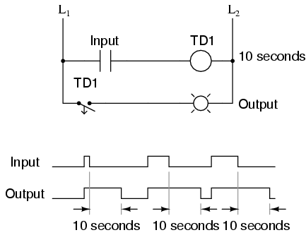
The monostable multivibrator, on the other hand, serves as a one-shot timer. It transitions to an unstable state for a predetermined duration when triggered, then returns to a stable state. This behavior is particularly useful for debouncing mechanical switches, where a single press can generate multiple transitions due to mechanical vibrations. The design often incorporates a single transistor, a resistor, and a capacitor to set the timing interval, which can be calculated using the RC time constant.
The bistable multivibrator functions as a memory element, maintaining its output state until an external trigger changes it. This configuration is crucial in digital electronics, forming the basis for flip-flops used in memory storage and data processing. The circuit employs two cross-coupled transistors, with inputs for setting and resetting the state, allowing it to hold information until explicitly changed.
In more advanced applications, the 555 timer IC is frequently employed as a multivibrator due to its reliability and ease of use. It can be configured in astable, monostable, or bistable modes, offering flexibility for various timing and oscillation tasks. The 555 timer incorporates internal comparators, flip-flops, and discharge transistors to enhance accuracy and stability, addressing the limitations of discrete multivibrator designs.
Overall, multivibrators are integral in creating oscillating signals, timing events, and storing binary information in electronic circuits. Their diverse configurations and applications make them fundamental components in modern electronics.A multivibrator is an electronic circuit used to implement a variety of simple two-state systems such as oscillators, timers and flip-flops. The most common form is the astable or oscillating type, which generates a square wave - the high level of harmonics in its output is what gives the multivibrator its common name.
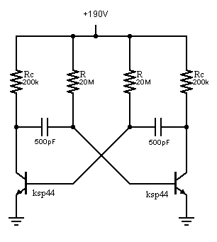
astable, in which the cir cuit is not stable in either state - it continuously oscillates from one state to the other. Another name for this type of circuit is relaxation oscillator. monostable, in which one of the states is stable, but the other is not - the circuit will flip into the unstable state for a determined period, but will eventually return to the stable state. Such a circuit is useful for creating a timing period of fixed duration in response to some external event.
This circuit is also known as a one shot. A common application is in eliminating switch bounce. bistable, in which the circuit will remain in either state indefinitely. The circuit can be flipped from one state to the other by an external event or trigger. Such a circuit is important as the fundamental building block of a register or memory device. This circuit is also known as a flip-flop. A similar circuit is a Schmitt trigger. In its simplest form the multivibrator circuit consists of two cross-coupled transistors. Using resistor - capacitor networks within the circuit to define the time periods of the unstable states, the various types may be implemented. Multivibrators find applications in a variety of systems where square waves or timed intervals are required, but the simple circuits tend to be fairly inaccurate, so are rarely used where precision is required.
An integrated circuit multivibrator, the 555, is very common in electronics. It uses a more sophisticated design to overcome some of the precision issues with the simpler circuits. When the circuit is first powered up, neither transistor will be switched on. However, this means that at this stage they will both have high base voltages and therefore a tendency to switch on, and inevitable slight asymmetries will mean that one of the transistors is first to switch on.
This will quickly put the circuit into one of the above states, and oscillation will ensue. Very roughly, the duration of state 1 (high output) will be related to the time constant R2. C1 as it depends on the charging of C1, and the duration of state 2 (low output) will be related to the time constant R3. C2 as it depends on the charging of C2 ” and these time constants need not be the same, so a custom duty cycle can be achieved.
However, the duration of each state also depends on the initial state of charge of the capacitor in question, and this in turn will depend on the amount of discharge during the previous state, which will also depend on the resistors used during discharge (R1 and R4) and also on the duration of the previous state, etc. The result is that when first powered up, the period will be quite long as the capacitors are initially fully discharged, but the period will quickly shorten and stabilise.
Need to expand this section. Similar to the astable/monostable but no capacitor, hence both of the states are stable. Need to add both inputs (set and reset) to the above circuit. 🔗 External reference
Related Circuits
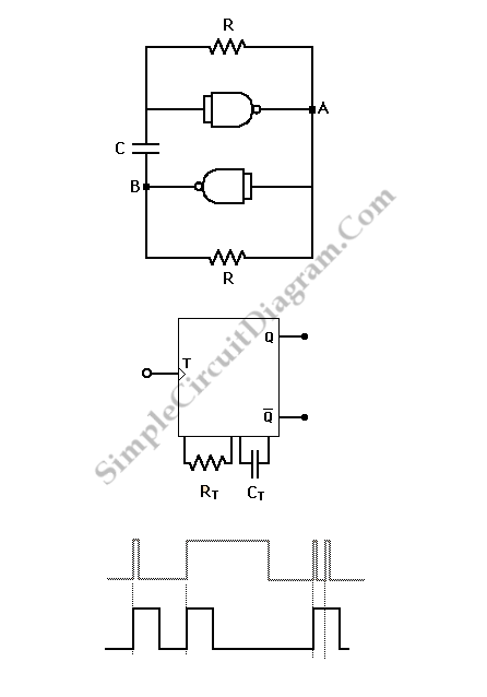
A monostable multivibrator is exemplified by the pulse detector within flip-flop circuitry, which briefly enables the latch portion during clock signal transitions. This device is classified as monostable due to its single stable state, which can maintain its output...
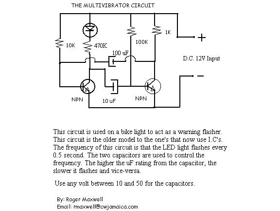
The resistor in series with the LED in the collector circuit of transistor T1 must be 470 ohms, not 470k. To connect a 24V-3W bulb, it is important to note that the resistance of this bulb when lit is...
Multivibrators are two-state devices that are extensively used in digital electronics. Bistable multivibrators, also known as flip-flops, serve as fundamental memory elements. Multivibrators can be categorized into three primary types: astable, monostable, and bistable. Each type has distinct operational characteristics...
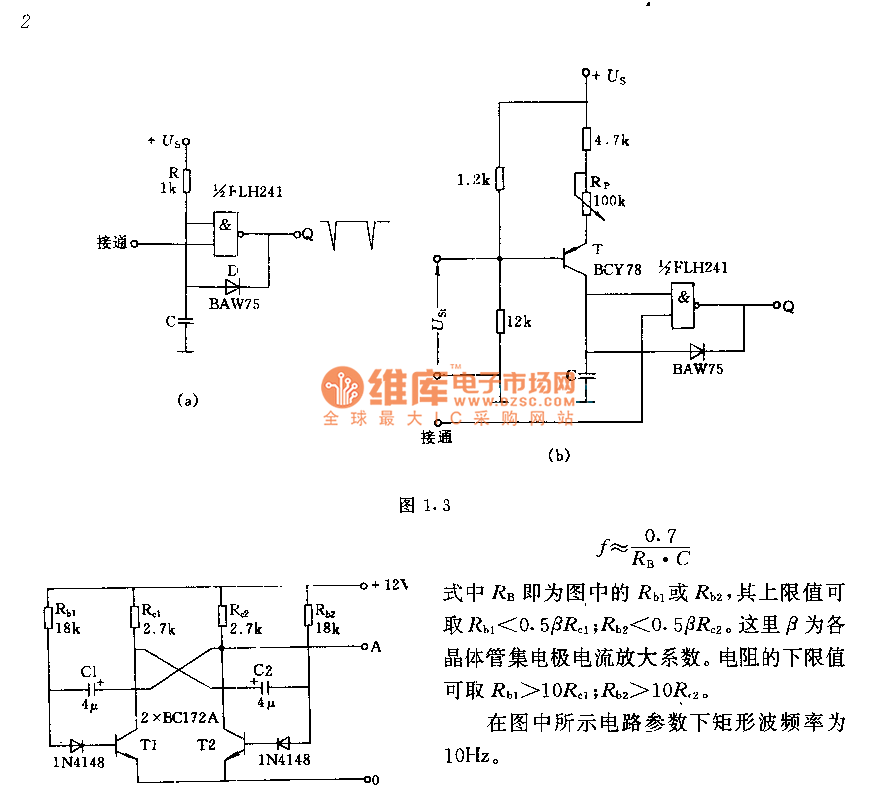
The circuit consists of two components whose parameters and models are designed to simultaneously generate a rectangular wave with a duty cycle of 1:1. The frequency is defined by the equation f = 0.7/(RB * C), where RB refers...
An oscillator is being developed to operate within the 200V range, targeting a frequency of approximately 1 kHz while minimizing current consumption. Initial testing has commenced. The design of a high-voltage oscillator capable of operating at 200V and generating a...

In a monostable multivibrator, one state is stable and permanent, while the other is temporary and quasi-stable. When an external trigger pulse is applied at the appropriate moment, the multivibrator transitions from the stable state to the quasi-stable state....