
8 digital LCD display driver circuit

The schematic features two ICM7211A devices, which are specifically designed for driving 7-segment displays. Each ICM7211A can control up to four 7-segment displays, allowing for a total of eight digits in this configuration. The BCD input signals are processed by the ICM7211A, which translates the BCD values into the corresponding binary signals necessary for driving the displays.
In this setup, the BCD data is fed into the input pins of the first ICM7211A, where it is converted into the appropriate signals for the first four digits (D1 to D4). The second ICM7211A receives additional BCD data for the remaining four digits (D5 to D8). The outputs from both ICM7211A chips are connected to the anodes or cathodes of the 7-segment displays, depending on whether a common anode or common cathode configuration is utilized.
Additional components may include resistors for current limiting, ensuring that the display segments do not exceed their maximum current ratings. Capacitors might also be used for power supply decoupling to maintain stable operation of the ICM7211A chips.
This digital tube display driver circuit is suitable for applications requiring clear visual representation of numerical data, such as in digital clocks, counters, or measurement devices. The use of BCD input signals simplifies the interfacing with microcontrollers or other digital logic circuits, enhancing the versatility of the design.Shows 8 digital tube display driver circuit, driven by the two ICM7211A, BCD / = binary data signal is sent to the BO-B3 ICM7211A end, select the digital signal divided into two groups were sent sentenced Dl ~ D4 end.
Related Circuits
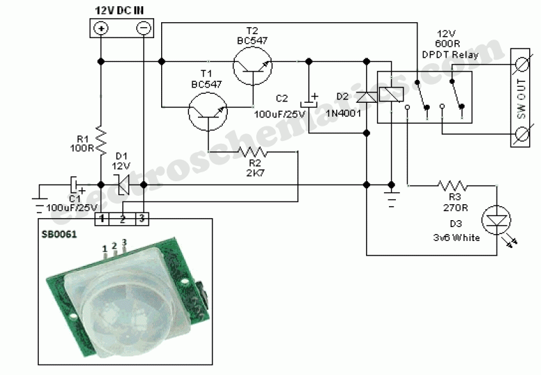
This circuit represents a general-purpose white LED security light equipped with a Passive Infrared (PIR) motion sensing mechanism. The core component of the circuit is the PIR sensor module SB0061, which is a pyroelectric sensor designed for human body...
Color sensing using a camera and a sufficiently powered processor that runs image histogram logic (or similar algorithms) can reliably determine the presence of specific colors. However, alternatives that are significantly more cost-effective for detecting the presence or absence...
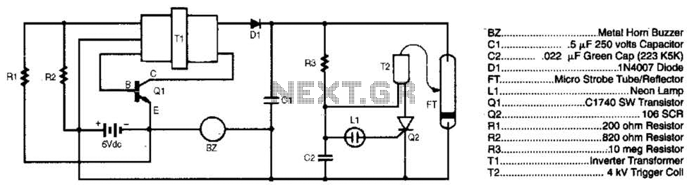
The burglar chaser is an effective accessory for any alarm system. It produces intense flashes of white light and generates a loud, irritating sound using a metal horn buzzer. Transformer T1 is connected to Q1, R1, and R2 to...
Power an RS232-TTL converter circuit using the serial port to eliminate the need for an external power supply. It has been noted that the DTR, RTS, and TD pins can facilitate this. Since the TD pin is already utilized...

The circuit operates as a light-to-sound conversion system, featuring a light electric sound conversion circuit with two simple fiber optic connectors for experimental purposes. The electrical diagram illustrates the conversion circuit, where audio signals from a radio, music player,...

To create a versatile and generic microcontroller board, the information provided thus far is sufficient. It covers the essential components needed to achieve this. The design of a microcontroller board requires careful consideration of various factors to ensure versatility and...