
Burglar Chaser Circuit
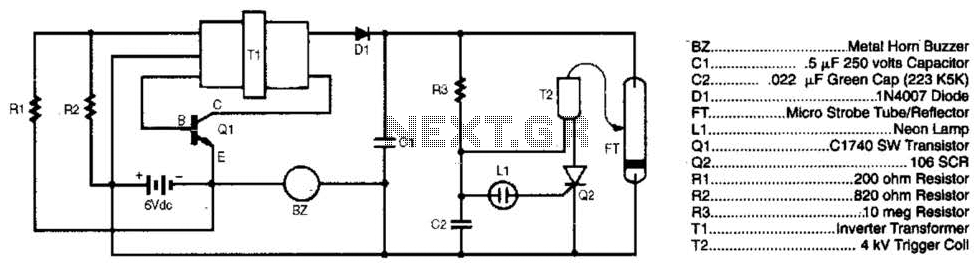
The burglar chaser circuit is designed to enhance security systems by integrating both visual and auditory deterrents. The core of the circuit involves a blocking oscillator formed by the components connected to transformer T1, which is pivotal in generating the required AC signal. The oscillator's output is a 6-Vac signal, which is crucial for the operation of the transformer. The transformer T1, with its high turns ratio, efficiently steps up the voltage to over 200 Vac. This high voltage is rectified by diode D1, converting the AC signal into a DC voltage suitable for further processing.
The DC voltage is stored in capacitor C1, which serves as a reservoir of energy for the circuit. Additionally, the neon relaxation oscillator, consisting of resistor R3, capacitor C2, and inductor L1, plays a critical role in the timing mechanism of the circuit. As capacitor C2 charges, it eventually reaches a breakdown voltage, ionizing L1 and causing SCR Q2 to trigger. This triggering action is essential as it allows the stored energy in C2 to be released rapidly.
The trigger coil is designed to amplify the voltage significantly, converting the 200 V from the circuit into a high-voltage pulse of 4000 V. This high-voltage pulse is necessary for the operation of the micro xenon strobe tube/reflector FT, producing intense flashes of light that serve as a visual alarm. The combination of the strobe light and the loud sound from the metal horn buzzer creates an effective deterrent against potential intruders.
The entire process is cyclical, with the system resetting itself after the strobe tube flashes, ensuring continuous operation until deactivated. This comprehensive design makes the burglar chaser a valuable addition to any alarm system, providing both visual and auditory signals to alert individuals of unauthorized access. The burglar chaser makes a great accessory for any alarm system. It creates brilliant flashes of white light and a loud, irritating sound from a metal horn buzzer. Transformer T1 is connected to Ql, Rl, and R2 to form a blocking oscillator. This creates a 6-Vac signal on the primary of Tl. Because of Tl`s large ratio of turns from primary to secondary, the 6-Vac signal is stepped up to a level of over 200 Vac, which is then rectified by Dl. The resultant dc voltage is applied to storage capacitor CI and the neon relaxation oscillator made up of R3, C2, and LI. Each time C2 charges up to a sufficient level, it ionizes LI, which causes SCR Q2 to fire. The firing SCR causes the charge on C2 to be applied to the trigger coil. The trigger coil converts the 200 V into the 4000-V pulse that is needed to fire micro xenon strobe tube/reflector FT.
The cycle repeats itself after the strobe tube flashes. 🔗 External reference
Related Circuits
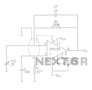
A charge amplifier is designed to amplify the signal charge from a piezoelectric device. It features a high internal impedance to accommodate the weak signal charge, which can be at the picoampere (pA) level. This necessitates a charge amplifier...
The completed Solar CD Two LED circuit is presented with components labeled to correspond with the schematic. Although the soldered circuit may appear different from the schematic, the connections remain consistent, which is crucial. To transition from the schematic...
A gas leak detector circuit that detects the leakage of LPG gas and alerts the user through audio-visual indications. The circuit operates off a 9V PP3 battery. A Zener diode is used to convert 9V into 5V DC to...
Here is a handy zener diode tester which tests zener diodes with breakdown voltages extending up to 120 volts. The main advantage of this circuit is that it works with a voltage as low as 6V DC and consumes...
This circuit includes a Relay Timer Circuit. One of the most commonly used circuits is that of the 555 Timer integrated circuit (IC). The circuit is designed to control a relay based on a timing interval. The Relay Timer Circuit...
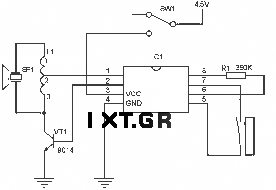
The alarm circuit operates as follows: When the power switch SW1 is turned on, the alarm system becomes active. If a magnet is brought close to the spring, the magnetic field attracts the spring, causing the dynamic and static...