
88 108 mhz pll controller for fm
The PLL controller unit is designed to ensure frequency stability in FM transmission by locking the output frequency to a reference frequency. The PIC16F870 microcontroller serves as the central processing unit, handling user input and controlling the display. The 2 x 16 character display provides user feedback, showing both the station name and the operating frequency, making it user-friendly.
The circuit includes buttons for frequency adjustment and character entry, enhancing user interaction. The soft and strong backlight options for the LCD cater to different user preferences and operational environments. The flexibility in component values, such as the potentiometer and resistors, allows for customization based on specific application requirements.
The PLL circuit utilizes the VCO to modulate the frequency based on the control voltage provided by the PIC microcontroller. This modulation ensures that the output frequency remains stable and accurate, which is essential for effective FM broadcasting.
Overall, this PLL controller unit represents a robust design for FM transmitters, combining ease of use with flexible configuration options, ensuring reliable performance in various operating conditions.This circuit will explain the PLL controller unit for the FM transmitter. It is very important since the transmitter frequency is digitally controlled and thereby very stable. The heart of this unit is a PIC processor called PIC16F870, a 2 x 16 char display and four buttons. If jumper J1 is disconnected the LCD will have soft backlight because a l ow current will pass through R6. If jumper J1 is connected you will have strong backlight. The component are not critial at all, the Pot (P1) can be from 1k-22k and (R1-R5) resistor can be changed to 1k-10k. The orange squars are the input from the buttons to select frequencies. The green squars are connection to the PLL at the VCO. The display has 2 lines with 16 Chars. The first line of the display show "FM Radio station", next line will show the frequency. If you want, you can write your own text on the first line. To modify the test, you press Inc 50 kHz button or Dec 50kHz button during power up. You can change the chars up/down with the two buttons. When you find thechar you like you press Inc 1Mhz button to go to next char. When all 16 Char is entered, the unit restart with the new text. 🔗 External reference
Related Circuits
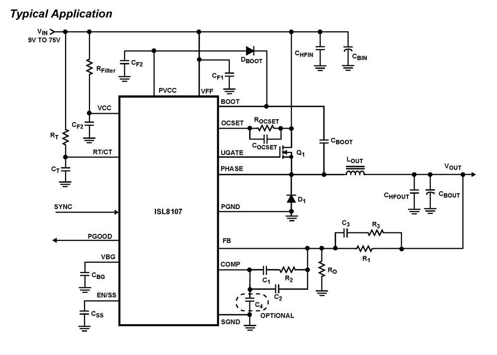
The ISL8107 is a single-phase, non-synchronous buck controller equipped with an integrated high-side MOSFET driver. It operates within an input voltage range of 9V to 75V. The internal reference voltage is 1.192V with a tolerance of ±1% across the...
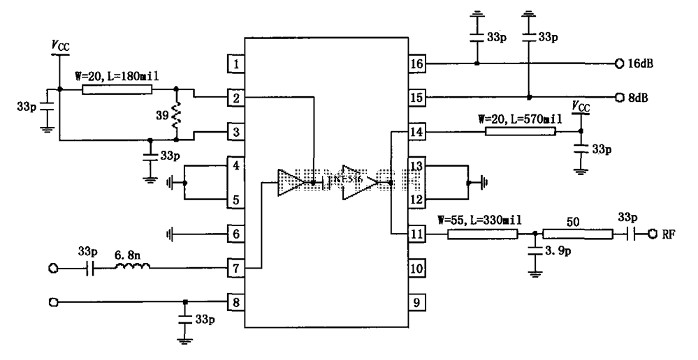
The circuit diagram illustrates the application of a 915MHz RF2155 power amplifier. The radio frequency (RF) signal enters through pin 7, where it is processed by a preamplifier. The output from the preamplifier is further amplified by the power...
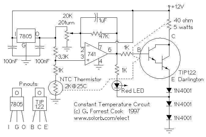
This circuit was built to stabilize a radio frequency VFO (Variable Frequency Oscillator) for ham radio applications. The circuit has also been used to lower the drift of a Ramsey FM10a micropower FM transmitter. More: The 7805 voltage regulator...
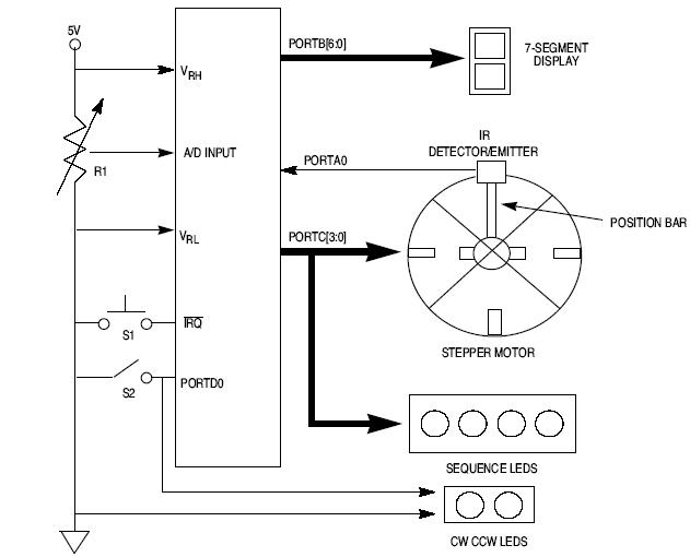
This article explains how to design a stepper motor system using an 8-bit Freescale microcontroller - MC68HC11E9. The design of a stepper motor system utilizing the 8-bit Freescale microcontroller MC68HC11E9 involves several key components and considerations to ensure effective control...
The following circuit illustrates a simple stepper motor controller circuit diagram. This circuit is based on the 7404 integrated circuit. Features include suitable heat dissipation. The simple stepper motor controller circuit utilizes the 7404 hex inverter IC to control the...
The circuit is built around two 555 timer ICs, U1 and U2. U1 is configured as a variable duty cycle oscillator with a constant time period of approximately 0.1 seconds. The duty cycle can be adjusted from 0 to...