
Simple Stepper Motor ControllerCircuit Based On The 7404 IC
The simple stepper motor controller circuit utilizes the 7404 hex inverter IC to control the operation of a stepper motor. The 7404 IC consists of six independent inverters, which can be employed to generate the necessary control signals for the stepper motor. The circuit operates by providing a sequence of pulses to the motor windings, allowing for precise control of the motor's position and speed.
In this configuration, the input signals to the 7404 can be generated by a microcontroller or a simple switch mechanism. The output from the 7404 drives the transistors that act as switches for the motor coils. When a logic high signal is applied to an inverter input, the output goes low, and vice versa, creating a square wave pulse that energizes the motor coils in a specific sequence.
To ensure adequate heat dissipation, it is essential to incorporate heat sinks or other thermal management solutions, especially if the circuit operates at higher currents. The design may also include diodes across the motor coils to protect against back EMF generated when the motor is de-energized, thereby preventing damage to the circuit components.
Overall, this simple stepper motor controller circuit provides an effective method for controlling stepper motors with minimal components, leveraging the capabilities of the 7404 IC for reliable operation.The following circuit shows about Simple Stepper Motor Controller Circuit Diagram. This circuit Based On The 7404 IC. Features: suitable heat .. 🔗 External reference
Related Circuits
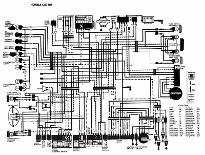
The following image illustrates the electrical wiring connection diagram for the Honda Motorcycle CB750F. It details the connections between various Honda components, including the right turn signal indicator light, oil pressure warning light, neutral indicator, high beam indicator, turn...
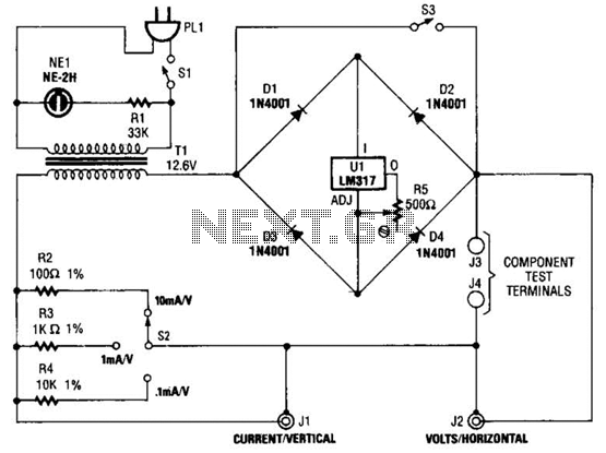
Useful for checking diodes, transistors, triacs, SCRs, resistors, and LEDs, this curve tracer should prove beneficial in the experimenter's lab. It displays the volt-ampere characteristic of a two-terminal device on an oscilloscope. This is a simple block diagram of...
The simplest Analog to Digital Converter (ADC) can be constructed as shown in Figure 1. The input voltage, which can range from zero up to the power supply voltage (Vcc), is converted to a parallel binary code at the...
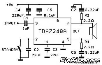
The following circuit diagram is a bridge amplifier specifically designed for car audio systems. The circuit is very simple, utilizing a few external components to support the power IC TDA7240A. This circuit will produce a maximum power output of... The...

This circuit is designed for sound detection and generates an output signal when sound is detected. This output can trigger another circuit that activates an alarm, making it suitable for security applications. The circuit employs a condenser microphone to...
The 555 IC is wired as an astable and the frequency is constant and independent of the duty cycle, as the total resistance (R charge + R discharge, notice the diode) is constant and equal to 22Kohm (giving a...
Warning: include(partials/cookie-banner.php): Failed to open stream: Permission denied in /var/www/html/nextgr/view-circuit.php on line 713
Warning: include(): Failed opening 'partials/cookie-banner.php' for inclusion (include_path='.:/usr/share/php') in /var/www/html/nextgr/view-circuit.php on line 713