
A 70cm Wide-band Transceiver Concept

The design of the 70 cm wideband transceiver emphasizes modularity, allowing for ease of maintenance and upgrades. Each module can be tested independently, which simplifies troubleshooting and enhances reliability. The use of a slow PLL for frequency stabilization is particularly advantageous in maintaining signal integrity over extended periods, ensuring that the transceiver can operate effectively in varying environmental conditions. The decision to implement buffer stages is crucial for preventing signal degradation during the transition between transmit and receive modes, thereby enhancing overall performance.
The choice of materials for the enclosures, such as tinned steel for the receiver and transmitter and cast aluminum for the power amplifier, is significant for thermal management and electromagnetic shielding. This helps to minimize interference and maintain signal clarity, which is critical in high-frequency applications. The modular design also allows for the potential integration of additional features in the future, such as advanced digital signal processing capabilities or enhanced user interfaces, should the demand for such functionalities arise.
In summary, this transceiver design is a comprehensive solution for modern packet radio applications, accommodating both current needs and future advancements in technology. The adaptability of the transceiver to function in various roles within the packet radio network, combined with its robust design and performance specifications, positions it as a valuable asset for users seeking reliable high-speed communication in the 70 cm band.This article presents a description of a 70cm wideband transceiver for duplex operation. The modules are designed for operation in a 200 kHz wide duplex channel, freely selectable from 430-440 MHz with a 100 kHz channel spacing. First prototypes were introduced on the international Packet Radio Symposium in April 1997. Some minor changes resulting from further experience were added to the text since then. Narrow-band packet radio net access frequencies with 25kHz channel spacing for operation with either 1k2 Baud AFSK or 9k6 Baud FSK are state-of-the-art and standard for over 15 years now. They are common in wide areas of Europe. These transmission speeds are sufficient for connecting local BBS systems, taking part in packet radio conversation groups or accessing DX clusters.
There are, however, new emerging applications requiring higher transmission speeds. These requirements ask for higher speeds of one order of magnitude compared to the standard 9k6 Baud operation. Examples for such applications are new BBS systes with HTML graphical user interfaces, digital voice transmission or image transmission in real-time following the ISDN standard.
Inter-node links following those requirements are currently being set up. High-speed user accesses to the packet radio network are still missing. In Germany, there is currently a single 70cm packet radio channel assigned for user accesses with a bandwidth of 200kHz. This channel has experimental status and the assignment of further channels cannot be foreseen. Therefore, the user TRX is designed as a single channel version without any user interface for changing the frequency.
The frequency however, should be changeable through re-programming. The transceiver must be adaptable to be used either as part of a digipeater or a user station. To utilise the benefits of high-speed operation, the transmit/receive delay should be smaller than 1 ms. The S/N at the receiver has to be 10 dB higher due to a wider bandwidth, if the access area requirements are similar to 9k6 operation.
This can be achieved by either increasing the transmit power by 10dB or the utilisation of an appropriate antenna gain. For user operation in unfavourable locations and on digipeaters, the authors recommend an output power of 20 Watts.
From experience, lower output power may be sufficient. Therefore, an alternative power amplifier is presented with an output power of 2-7 Watts. A transceiver concept was presented in [2] that meets the above requirements. First experience with prototypes and problems with parts availability and parts cost led to some minor design changes. The transmitter FSK signal is generated by modulating a VCO which is stabilised through a slow PLL to a frequency.
The loop filter of the PLL has a cut-off frequency of 40Hz, resulting in a minimum bit rate of 38k4 Baud. This slow PLL can only compensate for long-term drift caused by temperature- and ageing effects. Reactions, resulting from switching between TX and RX, have to be avoided. Therefore, a few buffer stages were added between the oscillator and the first switched stage. Also, the power supply of the individual stages has to be well decoupled. This can only be achieved with moderate efforts if the concept is divided in three separate modules: receiver, transmitter and power amplifier, all in separate boxes.
Only the power amplifier is switched between transmit and receive phases. Figure 1 shows the three blocks. Receiver, transmitter and the 7 Watts power amplifier are accommodated in tinned steel boxes of size 74 x 111 x 35 mm. The 20 Watts power amplifier is accommodated in a cast aluminium box with an attached heat sink, 120 x 95 x 34 mm in size.
The transmitter uses similar as in [1] a VCO operating on the output frequency. It uses a BF 979 transistor and a 20mm piece of semi-rigid cable as the oscillator inductance. The VCO is stabilised by the Siemens PLL circuit SDA 3302-5 🔗 External reference
Related Circuits
The receiver is based on a basic SA612 circuit. The local oscillator (LO) for the 20-meter band operates at approximately 9 MHz, with an intermediate frequency (IF) of 5.068 MHz. The IF filter employs two crystals and has a...
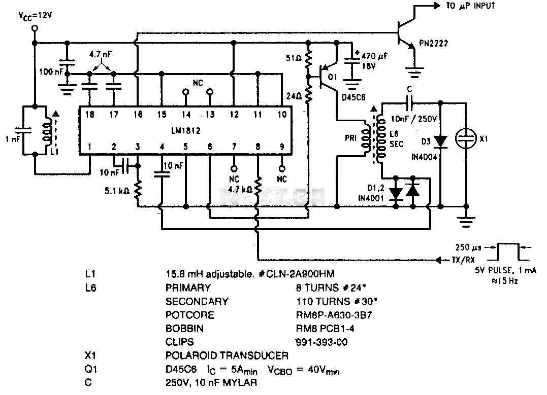
The LM1812 is a complete ultrasonic transceiver integrated circuit designed for various pulse-echo ranging applications. The chip functions by transmitting a burst of oscillations through a transducer, which is then used to listen for a return echo. If an...
The transceiver switches the four-element 1500-ohm crystal band-pass filter (BPF) connections between the inputs and outputs of two SA602 integrated circuits to reverse the signal flow for receive/transmit (R/T) operation. Since no intermediate frequency (IF) amplifier is utilized in...
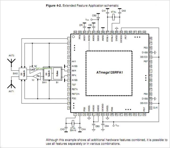
The ATR0981 is a monolithic integrated circuit (IC) produced using Atmel's advanced SiGe technology. This IC serves as a transmit and receive front-end solution, specifically designed for operation within a frequency range of 300 MHz to 500 MHz. It...
The primary feature of the transceiver described below is its simplicity while providing good performance at a minimal cost. The radio utilizes the MC3362 integrated circuit, which serves as an FM receiver with double conversion and includes nearly all...
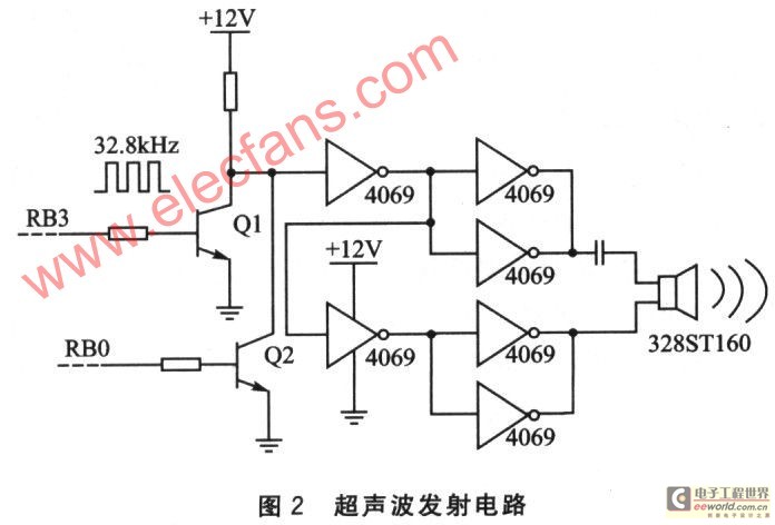
This device is based on the PIC16F628A microcontroller and utilizes a pair of independent ultrasonic transducers for both transmission and reception. It employs the Doppler effect to effectively detect whether someone enters a designated area and can control the...