
A Bedside Lamp Timer Circuit Schematic
The circuit operates primarily through the interaction of two integrated circuits, a relay, and a few passive components. The P1 pushbutton initiates the operation by applying power to the system, which triggers the relay to engage and subsequently powers the lamp. The LED serves as a visual indicator of the circuit's status, illuminating continuously during the initial 25 minutes and then entering a blinking mode to alert the user that the time is about to expire. The oscillation frequency of IC2 is critical for defining the timing intervals, with the resistor-capacitor (RC) timing network composed of R4 and C4 determining the overall duration of the lamp's operation.
The blinking pattern is a crucial feature, providing a clear signal to the user that the lamp will soon turn off, thus preventing abrupt darkness. The implementation of the ALL-ON ALL-OFF circuit using transistors Q1 and Q2 ensures that the system remains energy-efficient when not in use. The ability to extend the reading time by pressing P1 again offers convenience and flexibility to the user, while the option to turn off the lamp using P2 ensures user control over the device.
For further customization, the addition of a piezo sounder can enhance the user experience by providing audible alerts in conjunction with the visual LED signals. Adjustments to the timing can be made by selecting different values for R4 and C4, allowing for a tailored operation to suit individual preferences. Overall, this circuit is a practical solution for automating the control of a bedside lamp, enhancing comfort and usability for nighttime reading activities.The purpose of this circuit is to power a lamp or other appliance for a given time (30 minutes in this case), and then to turn it off. It is useful when reading at bed by night, turning off the bedside lamp automatically in case the reader falls asleep After turn-on by P1 pushbutton, the LED illuminates for around 25 minutes, but then it starts
to blink for two minutes, stops blinking for two minutes and blinks for another two just before switching the lamp off, thus signaling that the on-time is ending. If the user want to prolong the reading, he/she can earn another half-hour of light by pushing on P1.
Turning-off the lamp at user`s ease is obtained by pushing on P2. Q1 and Q2 form an ALL-ON ALL-OFF circuit that in the off state draws no significant current. P1 starts the circuit, the relay is turned on and the two ICs are powered. The lamp is powered by the relay switch, and IC2 is reset with a positive voltage at pin 12. IC2 starts oscillating at a frequency set by R4 and C4. With the values shown, pin 3 goes high after around 30 minutes, turning off the circuit via C3. During the c6 minutes preceding turn-off. The LED does a blinking action by connections of IC1 to pins 1, 2 & 15 of IC2. Blinking frequency is provided by IC2 oscillator at pin 9. The two gates of IC1 are wired in parallel to source more current. If required, a piezo sounder can be connected to pins 1 & 14 of IC1. Obviously, timings can be varied changing C4 and/or R4 values. 🔗 External reference
Related Circuits
The figure illustrates a preset outage timer circuit designed for an electric cooker. The timing range of the circuit extends from 1 hour to 12 hours, adjustable via a potentiometer (PR). The timing mode operates on a counting basis,...

This circuit can be utilized in intercom systems, walkie-talkies, low-power transmitters, and packet radio receivers. Transistors T1 and T2 constitute the microphone preamplifier. Resistor R1 provides the necessary bias for the condenser microphone, while preset VR1 serves as a...
A single-chip metal detector with a detection range of a few inches. This device is useful for identifying nails or screws in walls and floors, as well as locating buried mains cables. The core of the metal detector circuit...
This circuit is a simple IR detector for testing IR remote controllers. The circuit is based on one phototransistor which receives the IR beam. The NPN transistor works as an amplifier which feeds current to the LED. When this...
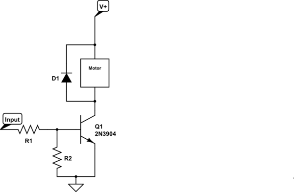
Control a small 5V motor using an external power supply by triggering a transistor with an Arduino. The transistor in use is an NPN type, specifically the 2N3904. To control a small 5V motor using an Arduino and an NPN...

The Jammer is a very small circuit and can fit inside a small plastic box with 9V battery inside. It can be very illegal if you attach an external antenna so don't. adjust frequency by turning trimmer. It is...