transistors Is this arduino motor driving circuit correct

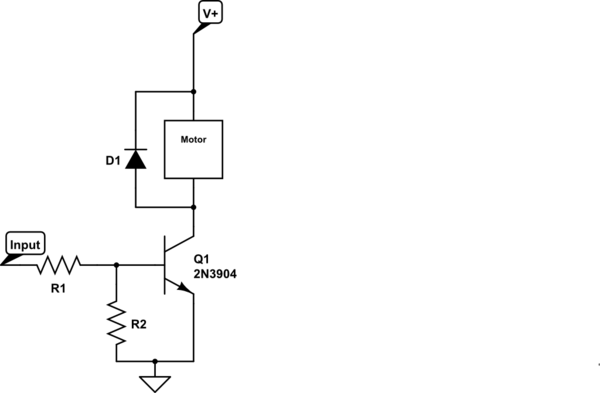
Control a small 5V motor using an external power supply by triggering a transistor with an Arduino. The transistor in use is an NPN type, specifically the 2N3904.
To control a small 5V motor using an Arduino and an NPN transistor such as the 2N3904, the following circuit configuration can be implemented. The Arduino will act as a control signal source, while the NPN transistor will serve as a switch to manage the motor's power from an external supply.
The circuit should be set up as follows:
1. **Transistor Configuration**: The 2N3904 transistor has three terminals: the collector (C), base (B), and emitter (E). The emitter should be connected to the ground (GND) of both the Arduino and the external power supply to ensure a common ground reference.
2. **Motor Connection**: The motor's negative terminal should be connected to the collector of the 2N3904. The positive terminal of the motor should be connected to the positive terminal of the external power supply, which should be rated at 5V.
3. **Base Resistor**: A resistor (typically between 1kΩ to 10kΩ) should be placed between the Arduino digital output pin and the base of the transistor. This resistor is crucial as it limits the current flowing into the base, protecting the Arduino from excessive current draw.
4. **Arduino Control**: The Arduino can be programmed to output a HIGH signal (5V) to the base of the transistor when the motor is to be activated. This will allow current to flow from the collector to the emitter, thus powering the motor. When the Arduino outputs a LOW signal (0V), the transistor will turn off, stopping the motor.
5. **Protection Diode**: It is advisable to place a flyback diode (such as 1N4001) across the motor terminals to protect the transistor from back EMF generated when the motor is turned off. The anode of the diode should be connected to the collector of the transistor, and the cathode should be connected to the positive terminal of the motor.
6. **Power Supply Considerations**: Ensure that the external power supply can provide enough current for the motor. The specifications of the motor should be checked to determine its current requirements under load.
This setup allows for safe experimentation with the motor without risking damage to the Arduino. Proper precautions, such as verifying connections and ensuring that the components are rated for the expected loads, should be taken to ensure successful operation.Control a little 5v motor from an external power supply by using the Arduino to trigger a transistor. Like this: Is that at all correct Will it work I want to experiment but I don`t want to break my new toy in the process.
The transistor I am using is an NPN, 2N3904. 🔗 External reference


