
A capacitance measuring circuit
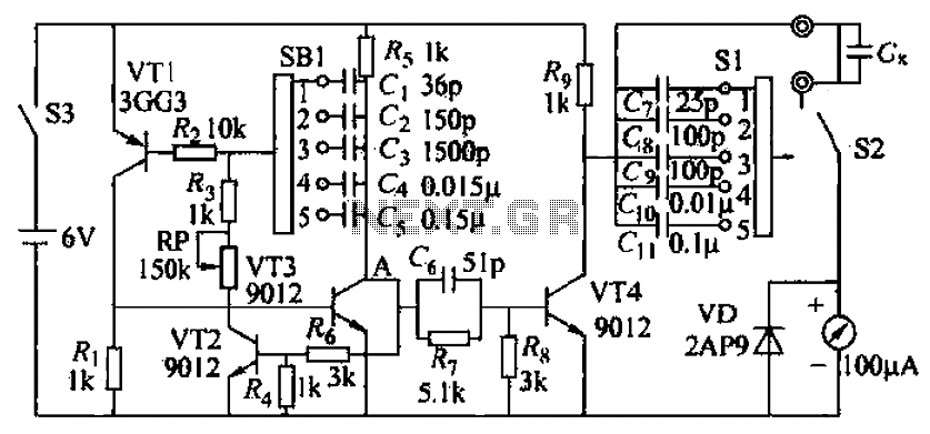
The capacitive measuring instrument operates on a linear measurement principle, enabling it to provide direct readings of capacitance values. The device employs a multivibrator configuration consisting of transistors VT1, VT2, and VT3, which work in tandem to generate a square wave signal that facilitates the charging and discharging of the measured capacitance. The frequency of this oscillation is influenced by the capacitance value being measured, with larger capacitances resulting in lower switching frequencies and vice versa.
The operation begins with the application of a power supply, which initiates the charging of capacitor C1. Initially, when the voltage across C1 is zero, transistors VT1 and VT2 remain in the off state, preventing current flow. As C1 charges, the voltage across it rises, eventually reaching a threshold that turns on VT1. This action causes VT2 to also conduct, allowing current to flow through the circuit. The output alternates between high and low states as the transistors switch, creating a square wave that is proportional to the capacitance being measured.
The instrument is equipped with various ranges for measurement, allowing it to accommodate a wide spectrum of capacitance values. The range selection switch (SB) enables the user to select the appropriate measurement range based on the expected capacitance. Calibration capacitors (C7-C11) are included to ensure the accuracy of the readings by allowing the user to calibrate the instrument before taking measurements.
To ensure the safety and longevity of the device, it is crucial to verify the absence of short circuits in the capacitors being tested. Utilizing a multimeter to check for shorts prior to measurement can prevent potential damage to the capacitive measuring instrument. This comprehensive approach to capacitance measurement makes the instrument a valuable tool in various electronic applications, providing reliable and precise readings across a wide range of capacitance values. Capacitive measuring instrument, b is the direct reading instrument measuring the capacitance of the circuit. The measuring instrument is capable of measuring a few picofarads to 0.1 microfarads electrical capacity, range into 25pF, lOOpF, lOOOpF, 0. Oll and 0.lvF fifth gear. Since the measurement principle is linear. Can directly meter readings scale. G charging, as shown by the solid line 5-21b 7F. When VT4 conduction, when the measured capacitance e and diode VI) discharge. VT4 switch once, the measured electrical capacitance to charge and discharge time. Measured capacitance large, each charge by the ammeter when more power. Also. VT4 second clock switch multiple times per second by electric ammeter amount more. Meter per second through the power, it is a current through the ammeter. Therefore, ammeter and current proportional to the measured capacitance, and switching VT4 proportional to the frequency. If the current through the ammeter requirements as large. So, when measuring small capacitance, VT4 the switching frequency will be higher. Transistor VT1, VT2, VT3 and the like complementary to renewable multivibrator. VT3 which is to improve the oscillation frequency of the circuit, when the circuit analysis can be considered as the collector emitter VT3 very short-circuited.
A power supply connected to the power supply input by Yan, wind, RP to cj charge, as shown by the solid line in Figure 5-21c. At the moment began. Ci zero voltage drop across, the hurricane voltage drop is small, can not make VT1 conduction. By the VT1 is in the OFF state, the voltage drop on R1 is small, so that VT2 also closed. A high point of the output potential. With C, charging, G on the voltage gradually increased, the left and right positive negative, so to a certain value after VT1 conduction.
Ri voltage drop on the increases, the Tuen VT2 conduction. A low point output bits. At this time, the power supply through VT1 emitter, base, Rz, VT2 collector emitter, c] to reverse charging, 5-21c is shown in dashed lines. With anti-c1 charging voltage cl is gradually increased, the left and right positive negative, and then to make a certain value VT1 deadline.
VT2 also cut dead, A fork point output high potential, C- returned to the charging process. So go on, A point constantly alternating high potential and low potential for controlling VT4s turned on and off. Connect different oscillation capacitance C. ~ C5: You can change the oscillation frequency, the switching frequency is changed VT4, to adapt to the measurement of different capacity needs.
C7-Cii is calibrated before measuring capacitance measured capacitance, first with the calibration capacitor to calibrate meter .RP use. in frequency tuning, calibration adjustment which enables full meter deflection is .SB pole five throw switch from SB1, SB2 composition, make range selection Turn the SB, the oscillation capacitance and calibration Pseudocapacitive corresponding to one or two.
for example, to measure a few capacitance hundred picofarads, first S2 to position calibration at .SB1 to 3, adjust RP, ammeter pointer to full deflection., then the measured capacitance connected to the red, the black terminal, and then dial the S2 to Survey Office. at this time, if the meter is lOOyA, the line and the needle drops 56FcA place, then the measured capacitance is 560pF.
If the measured capacitance range is not clear, first with the largest measuring range, etc. judged range and then with a suitable measuring range. before measuring, it is best to use one hundred multimeter ohm file, determine whether there is a short circuit current measured capacitance like. Do not use this instrument to measure short-circuited capacitor, doing so can damage the meter.
Related Circuits
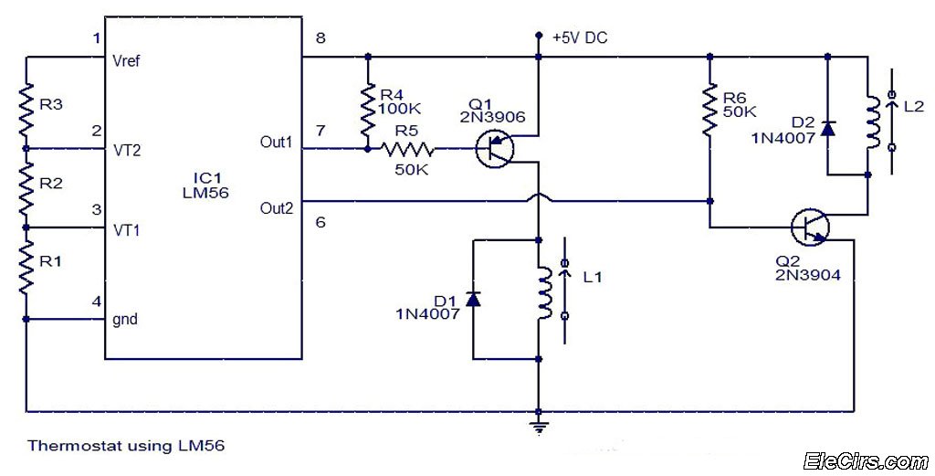
The LM56 Thermostat Project Circuit Diagram includes a schematic for the LM56 thermostat. The values of resistors R1, R2, and R3, which determine the required trip points VT1 and VT2, can be calculated using the following equations: VT1 =...

This circuit utilizes the Mitsubishi M65830 Digital Delay chip, which has proven to be simple and effective for applications requiring a fixed delay. The serial data necessary for achieving various delay settings is not readily available and would significantly...
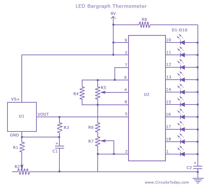
An LED thermometer that can function as a temperature sensor or temperature measurement circuit, utilizing the LM34 for Fahrenheit display or the LM35 for degree Celsius display. The LED thermometer circuit is designed to provide accurate temperature readings using either...
This scheme is a Standing Wave Ratio (SWR) meter, which is relatively simple and can be easily constructed. Once a directional coupler is created, the results will be indicated on the measuring LED meters as a ratio of SWR. The...
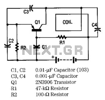
The metal locator utilizes a one-transistor oscillator in conjunction with an AM radio to detect metal. Transistor Q1 is a PNP transistor connected to the oscillator circuit. Resistor R1 supplies the appropriate base bias, while capacitors C3 and C4,...
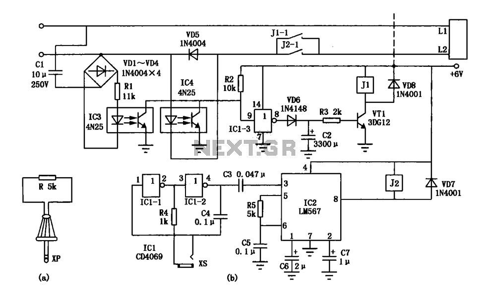
An electronic lock utilizing a telephone key, which is connected through a resistor plug, is integrated after the oscillator circuit's startup phase. The accuracy of the oscillation frequency determines whether the phone can be used for outgoing calls, while...