
delay circuit for surround sound

The Mitsubishi M65830 Digital Delay chip serves as the core component in this circuit, designed for applications where a consistent delay is essential. This chip is well-regarded for its reliability and straightforward configuration, making it suitable for various audio processing tasks. The circuit's design adheres closely to the specifications outlined in the Mitsubishi data sheet, ensuring that it meets performance expectations across a wide frequency spectrum.
The tuning of the filters to approximately 9.5 kHz is a critical aspect of this design, as it aligns with the frequency range typically associated with rear channel audio output. Maintaining this tuning is advisable, as it has been determined to provide the best audio fidelity for the intended application. Altering the filter frequency may not yield significant benefits and could potentially degrade performance.
The internal operational amplifiers within the circuit facilitate the necessary signal processing while minimizing the need for additional external components. This design choice simplifies the assembly process and enhances reliability, as fewer components generally lead to reduced points of failure. The construction of the circuit as a module allows for straightforward integration into larger systems, requiring only a 5 Volt power supply and appropriate connections for both analog and digital ground, as well as input and output connections.
Overall, this circuit exemplifies an efficient and effective approach to implementing digital delay in audio applications, leveraging the capabilities of the Mitsubishi M65830 chip while ensuring ease of construction and optimal performance for rear channel audio systems.This circuit in below uses the Mitsubishi M65830 Digital Delay chip. This has been around for a while now, and is simple and effective (provided that a fixed delay is acceptable). The serial data required to obtain different delay settings is not easily obtained, and would add considerably to the complexity of the circuit.
This is the figure of th e circuit. The circuit is (almost) a direct adaptation from the Mitsubishi data sheet, and as shown will give good performance over a wide frequency range. The filters are tuned to around 9. 5 kHz, and although this could be reduced there does not seem to be any good reason to do so. This seems to be the optimum response for rear channel speakers, so should be left alone. The filter circuits use internal op amps, and only require the external components. The unit can be constructed as a module quite easily, requiring a 5 Volt supply, analogue and digital earth connections, and an input and output.
🔗 External reference
Related Circuits
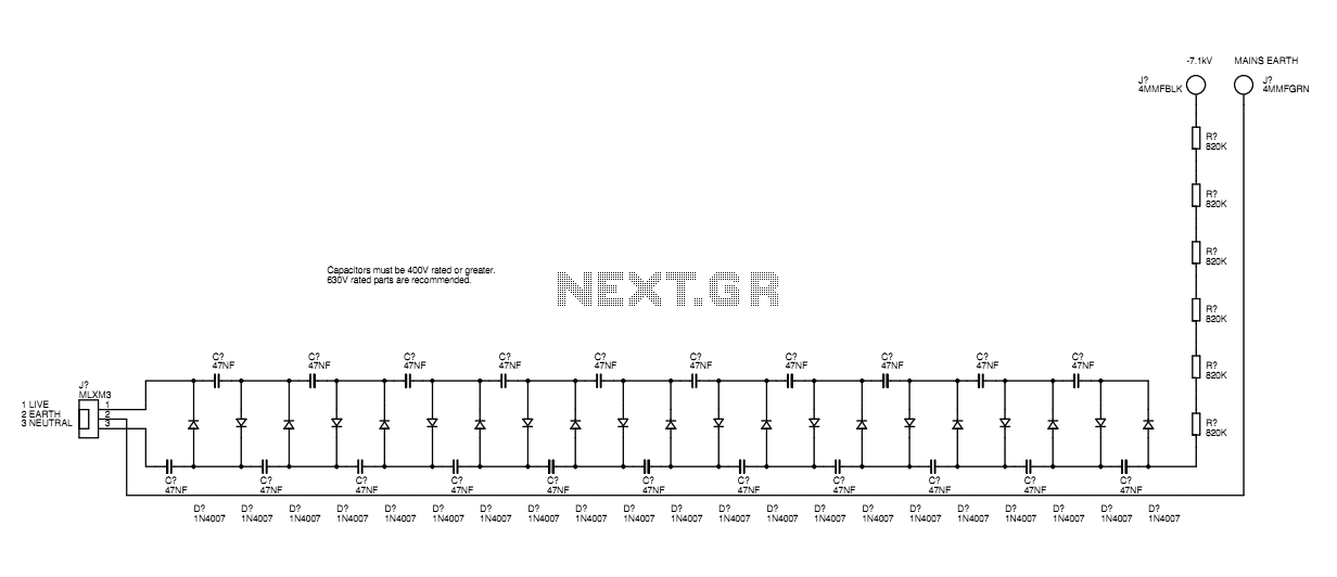
A basic mains driven Cockroft ladder high voltage generator is shown in the schematic. This is functionally the same as a project in Electronics Today International many years ago. The peak mains voltage of 340V appears across each capacitor...
This is a metronome circuit that features a mechanical sound character. A metronome with a mechanical sound character enhances the experience and enjoyment of musical practice. The metronome circuit is designed to produce rhythmic sounds that assist musicians in maintaining...

This circuit is simple and inexpensive, which is its primary advantage. Although the output power is not high, the audio quality is good due to the TDA1910's low noise characteristics. This circuit is suitable for use as a student...
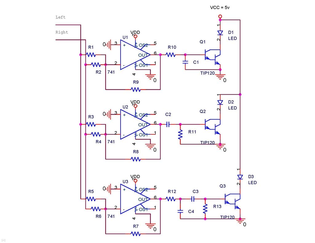
It is possible to synchronize the LEDs so that the speakers continue to play loudly while the LEDs are not always illuminated during music playback. The individual has a solid understanding of electrical concepts and is seeking a method...
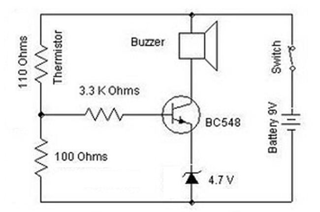
A heat sensor circuit can be utilized to control any device using a heat sensor. In this circuit, a thermistor and a resistor are connected in series, forming a potential divider circuit. The thermistor is of the Negative Temperature...
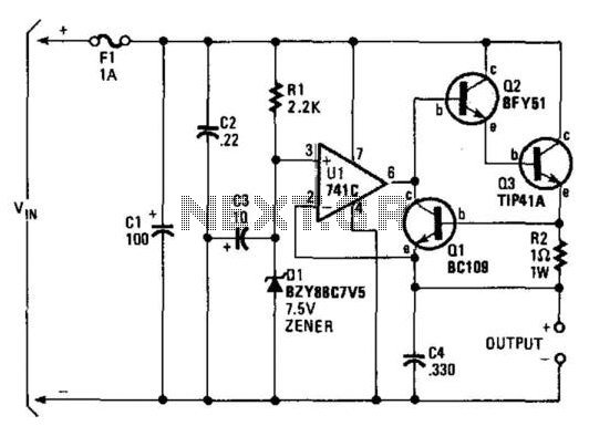
A regulator enables the powering of a 7.5-V cassette recorder or other devices from a 12-V DC automotive system. The circuit can provide approximately 600 mA of current. Q3 requires a heatsink due to its potential to dissipate up...
Warning: include(partials/cookie-banner.php): Failed to open stream: Permission denied in /var/www/html/nextgr/view-circuit.php on line 713
Warning: include(): Failed opening 'partials/cookie-banner.php' for inclusion (include_path='.:/usr/share/php') in /var/www/html/nextgr/view-circuit.php on line 713