
A circuit diagram of a switching power supply

The schematic for the switching power supply includes a transformer with a secondary winding, which is responsible for stepping down the voltage. The output from this winding feeds into the rectifier circuit, which consists of diodes, including VD4, that convert the AC voltage to DC. The filter capacitors, C22 and C23, are critical components that smooth out the rectified output, ensuring a stable DC voltage. The design of the power supply must account for thermal management due to the compact layout within the monitor's base. The proximity of the capacitors to the rectifier diode leads to increased thermal stress, which can accelerate the aging process of the capacitors.
In this scenario, the failure of C22, due to its significant drop in capacitance, has a direct impact on the stability of the 12V output. The power supply's ability to maintain stable voltages for the 5V and 3.3V outputs is a result of their respective regulation circuits, which may compensate for fluctuations in the input voltage. However, the underlying issue with the 12V output remains a concern, as it can lead to potential operational failures in devices relying on this voltage level. Regular maintenance and monitoring of the power supply components, especially in heat-sensitive environments, are essential for ensuring long-term reliability and performance.12V voltage instability, you should first check the switching power supply output section, as shown in FIG. The secondary winding of the transformer and the switch VD4 examination were normal, no inductor L2 Weld phenomenon. Filter capacitors C22 and C23 parameters are 1000pF / 16V, measuring capacitance meter C23, normal (capacity decreased slightly), but the C22 capacity has dropped to less than 80 F, the C22, C23 with the analysis of the reasons is the machine's main power mounted within the base of the monitor, the space is small, poor heat dissipation, and C22, C23 are close to 12V rectifier diode (especially C22 closer together), decreased capacity after being baked to make 12V with a load capacity deteriorates, and then this failure. Although derived from the 5V and 3.3V 12V, 12V instability but not down to 5V and 3.3V supply voltage converter limit or less, so the two voltages have been normal, and thus conceal the nature of the fault.
Related Circuits
These two tank circuits appear to broaden the operating spectrum. The accompanying information sheet indicates that when both circuit stages oscillate at the same frequency, the power output reaches its maximum. This suggests that if the tunable tank circuit...
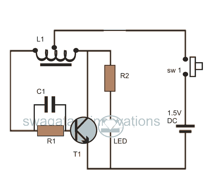
This post discusses blue and white LED drivers utilizing a joule thief circuit. Further exploration of the circuit's functionality is provided, along with simulation points. The joule thief circuit is a simple and efficient boost converter that allows for the...
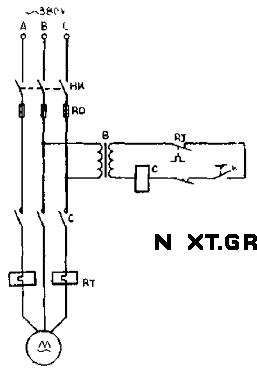
The gear lathe is unloaded from the stop line as depicted in the figure. When the turning clutch is in the stop position, the limit switch XWK is disengaged, which immediately powers the AC contactor coil C to stop...
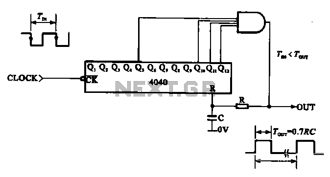
This document illustrates the application of a CMOS integrated circuit (IC) count divider, specifically the TC4040, which functions as a 12- or 14-bit counter. The circuit can be configured to achieve various frequency division ratios, such as a 1:3600...
Amplifier with IC number TDA7293 for processing sound systems. This amplifier includes inputs for a radio, TV, stereo, or other line-level devices. It also features a phono input for a record player, guitar, microphone, or other unamplified sources. With...
A two-diode selector circuit is utilized when the primary voltage source exceeds both the diodes' turn-on voltage and the input voltage of the second diode. Schottky diodes are preferred due to their low turn-on voltage (typically 0.4V) and high...