
two stage fm transmitter bug more tank circuits
The circuit configuration described involves two tank circuits functioning to extend the operational frequency range of the system. Tank circuits, which consist of inductors and capacitors, resonate at specific frequencies and are critical for tuning and filtering applications in radio frequency (RF) circuits. The interaction between the tunable tank circuit and the other two circuits is essential for achieving optimal power output, particularly when all circuits are synchronized to oscillate at the same frequency. This synchronization maximizes energy transfer and efficiency, thereby enhancing transmission capabilities.
The parallel arrangement of the resistor and capacitor below the transistor serves a crucial role in signal processing. The resistor, connected to ground, helps stabilize the circuit by providing a discharge path for the capacitor. The capacitor's placement, while not directly linked to the tank circuit outputs, is significant as it influences the AC signal behavior by allowing certain frequencies to pass while shunting others to ground. This selective filtering can help mitigate unwanted noise and improve signal integrity.
The decision to omit the capacitor connection to the antenna line, as seen in FM Transmitter 1, raises important considerations regarding circuit design. The specific orientation of the 47pF capacitor could be intended to optimize the circuit's response to particular frequency ranges or to prevent loading effects that could impair the overall performance of the transmitter.
Furthermore, the inclusion of a radio frequency choke (RFC) is vital for maintaining the integrity of the circuit by preventing high-frequency AC signals from interfering with the operation of other components. The RFC achieves this by introducing inductive reactance, which effectively blocks unwanted high-frequency signals while allowing lower frequencies to pass, thus ensuring that the desired signals are transmitted without distortion.
Overall, the described circuit illustrates a sophisticated approach to RF design, combining tank circuits, selective filtering, and impedance management to achieve efficient and effective signal transmission in radio frequency applications.These two tank circuits seem to expand that operating spectrum. Maybe The information sheet that came with the bug states that When both circuit stages are oscillating at the same frequency, the power output will be at a maximum. This must mean that if the tunable tank circuit is at the same oscillating frequency as the two other tank circuits, that enables better utilization
of the power and therefore farther transmission. So then south of the transistor we see that there`s a resistor and capacitor in parallel. The orientation of these two elements is slightly confusing to me, but it is still somewhat functionally the same as in FM transistor 1: The resistor is connected to ground in both instances, but the capacitor in FM Transmitter 2 is not connected to the tank circuit outputs. It still does allow current going through the transistor to go through to ground. So my first question is why is the 47pf capacitor in the orientation/location it is in besides allowing certain signals to go to ground.
Why wouldn`t it be connected to the antenna line as in FM transmitter 1 So an RFC Choke is also known as a radio frequency choke. These are inductances that prevent certain high radio frequencies from certain areas of a radio circuit.
Remember that the inductors prevent AC current from passing through due to reactance. 🔗 External reference
Related Circuits
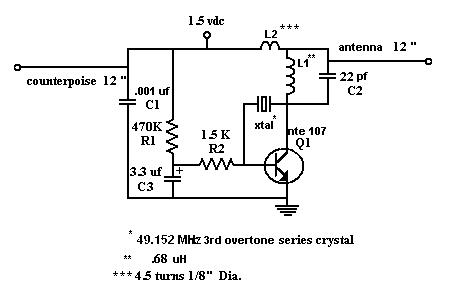
The M15m Tracking Transmitter is a modified version of the M15 Animal Tracking Transmitter. It has been designed to operate on 147.460 MHz using an inexpensive 49.152 MHz computer crystal and is intended for printed circuit board construction. The...
This circuit is a small +5V power supply, which is useful when experimenting with digital electronics. Small inexpensive wall transformers with variable output voltage are available from any electronics shop and supermarket. Those transformers are easily available, but usually...
This document provides a schematic and description for constructing an FM transmitter. The circuit is designed to be simple, utilizing minimal components while achieving a long transmission range. The FM transmitter circuit typically consists of a few key components: an...
This set of two circuits forms the basis for a simple light wave transmitter. A laser beam is modulated and directed towards a receiver that demodulates the signal and presents the information, such as voice or data. The assembly...

An FM and AM transmitter integrated into a compact device utilizing the CD4001 integrated circuit. It broadcasts at 20 MHz for AM and 100 MHz for FM. The described transmitter combines both Frequency Modulation (FM) and Amplitude Modulation (AM) capabilities...
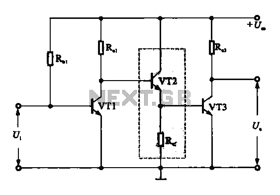
A DC-coupled multi-stage amplifier circuit consists of multiple stages of amplification using a DC-coupled configuration. Each stage utilizes NPN-type transistors, which are designed to maintain appropriate operating points at the base of each stage. As the signal progresses through...