
A common collector amplifier
The common collector amplifier, also known as an emitter follower, is a three-terminal electronic circuit configuration that provides high input impedance and low output impedance. The circuit typically consists of a single NPN or PNP transistor, with the emitter terminal serving as the output. The input signal is applied to the base terminal, while the output is taken from the emitter terminal, making the circuit an effective buffer.
In this configuration, the biasing of the transistor is crucial for maintaining proper operation. The two bias resistors connected to the base are typically chosen to ensure that the transistor operates in the active region, allowing for linear amplification of the input signal. The values of these resistors can be calculated based on the desired quiescent current and the transistor's characteristics.
The load resistor connected to the emitter is responsible for setting the gain of the amplifier. The gain of a common collector amplifier is approximately equal to one, meaning that the output voltage closely follows the input voltage but with a lower output impedance. This characteristic is particularly useful in applications where impedance matching is necessary, such as driving low-impedance loads or interfacing with other circuit stages.
The capacitors in the circuit perform vital roles in AC coupling. They block any DC component of the input signal while allowing the AC component to pass through. This ensures that only the desired AC signal is amplified, preventing any DC offset from affecting the operation of subsequent stages in the circuit.
In summary, the common collector amplifier is a versatile and widely used configuration in electronic circuits, offering benefits such as impedance matching, buffering capabilities, and signal integrity. Proper selection of components and biasing techniques is essential for optimal performance in various applications, including audio amplifiers, signal conditioning, and interfacing circuits.A common collector amplifier (1) common collector amplifying circuit structure and key components of common collector amplifier circuit as shown, the key components of the comp osition and common emitter amplifier circuit is basically the same, except there are two: One is the collector resistors Mu to the emitter (indicated by Van), and the second is the output signal from the collector but no longer taken from the emitter. In this circuit, two adjacent bias resistor R l and it is through the power supply to the base of the transistor (b) power supply: Rc is the transistor emitter (e) of the load resistor; two capacitors are played through exchange compartment DC coupling capacitor effect: the resistor Rr is a minus plant output signal load resistor.
Common-emitter transistor amps, NPN and PNP type transistor amplifier Sheng also big differences between different power supply. Since the transistor amplifier circuit of the power supply resistance is very small, the AC signal is equivalent to a short circuit between positive and negative.
Equivalent AC power supply, i.e. the collector of the transistor (c) corresponds to the ground. The input signal is loaded into the base of the transistor (b) and polar (e) and the emission load resistor between Burgundy, loaded into the base of the transistor (b) and collector (c) it is equivalent to between the output signal from the transistor emitter electrode (e), it is equivalent to between transistors from the pole (e) and collector (c) emission and therefore the collector (c) for the input signal and the output signal common terminal number, it is called common collector electrode amplifier.
Related Circuits
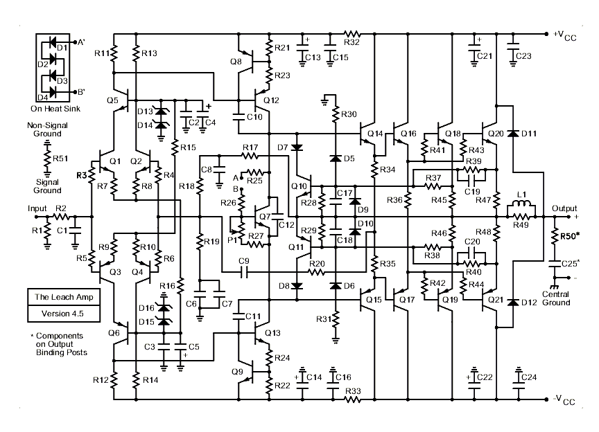
A hot topic of amplifier design in the 1970s was "transient intermodulation distortion" (TIM). Other names which were used for this phenomenon were "slewing induced distortion" (SID), and "dynamic intermodulation distortion" (DIM). TIM occurs when a transient input signal...
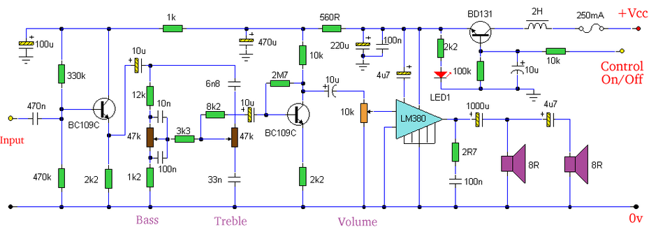
Built around an LM380, this amplifier includes tone controls and electronic soft switching. The soft switching circuitry ensures power is balanced. The LM380 is a power audio amplifier capable of delivering up to 14 watts of output power. It is...
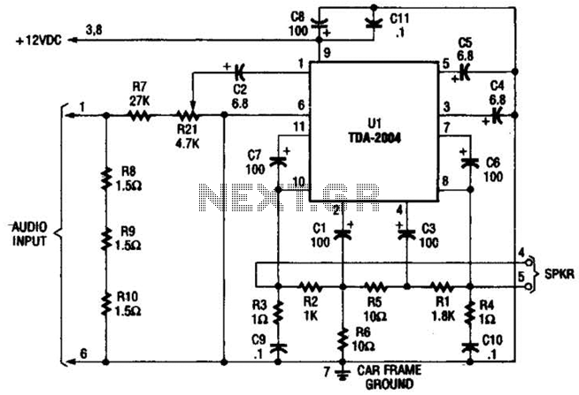
Only one channel of this circuit is shown. The other is practically identical. The input to the circuit, taken from the speaker output of a car radio, is divided into two paths. In one path, a high-power divider network...
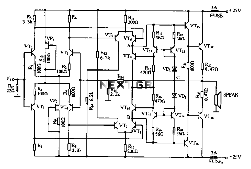
The CL type circuit is not a power amplifier output capacitance, feedback capacitance, or compensation capacitor amplifier circuit; it operates solely through a transistor (or FET) and a resistor. This circuit can generate feedback, and phase shift elements are...
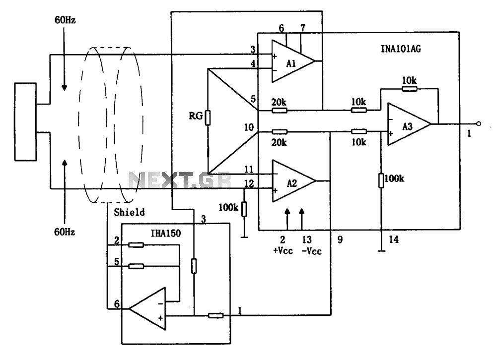
The circuit diagram illustrates a hum elimination instrument amplifier circuit. The amplifier stages A1 and A2 utilize the integrated operational amplifier INA101, followed by stage A3 which employs the INA105. A feedback circuit is incorporated to reduce the power...
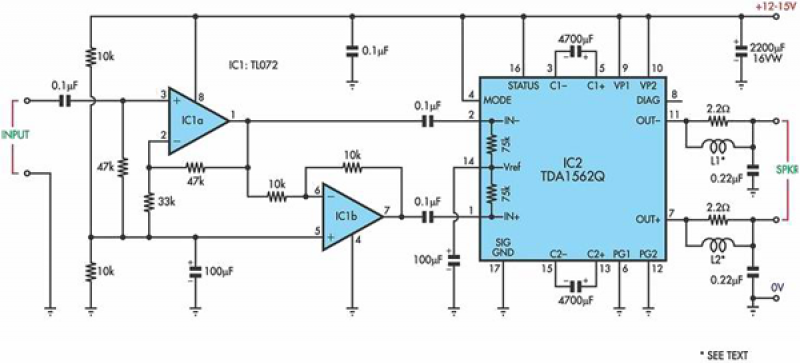
This circuit is based on a Philips class-H audio amplifier integrated circuit (IC) and can deliver 36W RMS or 70W music power, all from a 13.8V supply. The Mighty Midget Amplifier is capable of providing approximately 36W RMS continuous...
Warning: include(partials/cookie-banner.php): Failed to open stream: Permission denied in /var/www/html/nextgr/view-circuit.php on line 713
Warning: include(): Failed opening 'partials/cookie-banner.php' for inclusion (include_path='.:/usr/share/php') in /var/www/html/nextgr/view-circuit.php on line 713