
Booster Amplifier For Car Stereo Use Circuit
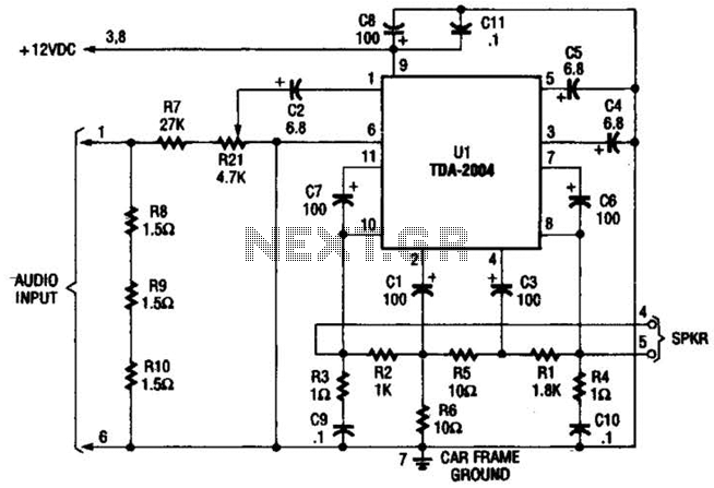
This circuit is designed to enhance audio output from a car radio by utilizing a single-channel TDA-2004 audio power amplifier. The circuit architecture begins by taking the speaker output from the car radio, which is typically a low-level audio signal. This signal is then divided into two distinct paths to optimize performance and ensure compatibility with the radio's output characteristics.
The first path employs a high-power divider network consisting of resistors R8, R9, and R10. This network is critical for matching the input impedance of the amplifier circuit to the output impedance of the car radio, which is essential for maximizing power transfer and minimizing signal distortion. The specified resistance of 4.5 ohms is carefully chosen to provide a balanced load for the radio's output stage.
In the second path, the audio signal is routed through resistor R7, trimmer potentiometer R21, and capacitor C2. The potentiometer allows for fine-tuning of the signal level before it reaches the amplifier, providing flexibility in adjusting the gain. The combination of R7 and R21 provides a minimum resistance of 27,000 ohms, which is necessary for proper operation of the amplifier while ensuring that the input signal is adequately conditioned.
The TDA-2004 integrated circuit serves as the core amplification component. It is specifically designed for automotive applications, providing robust audio amplification with low distortion. The amplified output is available at pins 8 and 10 of the IC, which are connected to the loudspeaker. The design emphasizes that the amplifier is intended for use only with car radios that have speaker outputs referenced to ground, as using it with radios that have balanced outputs could lead to improper functioning or damage to the circuit.
Overall, this circuit exemplifies an effective approach to enhancing car audio systems, leveraging a combination of impedance matching, signal conditioning, and amplification to deliver improved sound performance. Only one channel of this circuit is shown. The other is practically a carbon copy.The input to the circuit, taken from your car radio`s speaker output, is divided along two paths; in one path, a high-power divider network (consisting of R8 through R10) provides 4.5- resistance to make the circuit`s input impedance compatible with the output impedance of the car radio. In the other path, the signal is fed to the input of Ul through resistor LR7, trimmer potentiometer R21, and capacitor C2.
Together, R7 and R21 offer a minimum resistance of 27,000 .Integrated circuit Ul (a TDA-2004 audio power amplifier) amplifies the signal, which is then output at pins 8 and 10 and fed to the loudspeaker. Note: This amp is designed for use only with car radios whose speaker outputs are referenced to ground: do not use it with radios that have balanced outputs. 🔗 External reference
Related Circuits
This FM transmitter (FM Tx) is about the simplest and most basic FM Tx it is possible to build and have a useful transmitting range. It is surprisingly powerful despite its small component count and 3V operating voltage. It...
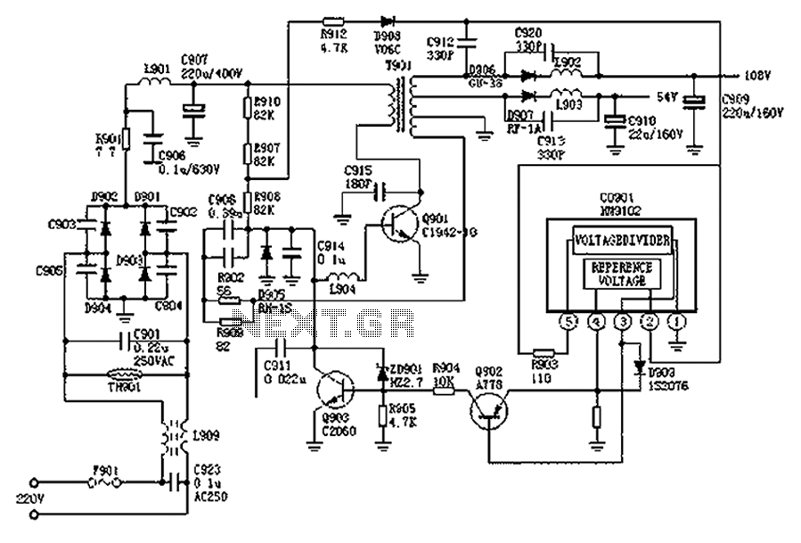
The Hitachi NP8C switching power supply circuit is illustrated in FIG. The Hitachi NP8C power models include CTP236, CEP320D, CRP350D, 450D, Furi HFC-236, 450, and Venus C37-401, C46-1, C563, among others. This circuit was widely used in early Chinese...
There are many individuals interested in listening to frequencies within the VHF range of 108 to 132 MHz. This VHF AM converter is designed to convert signals from a frequency band of 106 to 150 MHz, allowing users to...
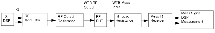
The 3GPPFDD_UE_RX is a test bench designed for testing the user equipment receiver in 3GPP FDD systems. It allows users to connect to an RF circuit device under test (DUT) and evaluate its performance through predefined measurements. This test...
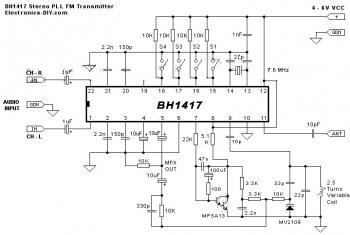
The circuit diagram of a stereo PLL FM transmitter based on the BH1417 chip is presented. This recent design from RHOM integrates numerous capabilities within a compact package. It features pre-emphasis and a limiter to maintain consistent audio levels...
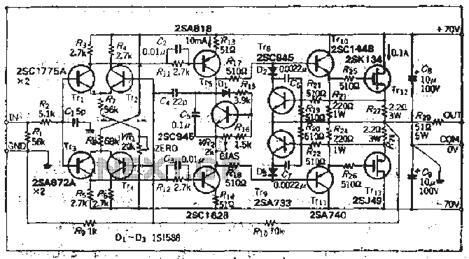
The south circuit consists of four parts, arranged in descending order: an NPN transistor dynamic garbage device (T1), a PNP transistor differential amplifier (T2, T3) forming a double differential circuit, two balanced output amplifiers with opposite phase, and a...
Warning: include(partials/cookie-banner.php): Failed to open stream: Permission denied in /var/www/html/nextgr/view-circuit.php on line 713
Warning: include(): Failed opening 'partials/cookie-banner.php' for inclusion (include_path='.:/usr/share/php') in /var/www/html/nextgr/view-circuit.php on line 713