
A Mini Payphone Controller in order to use coins in three slot pay telephones
To facilitate assembly, users are encouraged to salvage wires with spade lugs from old wiring harnesses. For Western Electric payphones, four color-coded wires, each 10 inches long, need to be connected to specific output terminals on the printed circuit board. Additionally, a 12-inch jumper wire with spade lugs on both ends is required. The coin relay and internal hopper parts for single slot Western payphones are compatible with those from older three-slot models. Modification of the coin relay is necessary, which involves removing screws and making mechanical adjustments for easier operation. The tools required for this process include pliers, wire cutters, a soldering iron, solder, and a screwdriver.
Testing the modified coin relay and hopper assembly is straightforward. An ohmmeter, a modular phone cord, and a nickel are needed for this process. The assembly must be connected to a working phone line to verify its functionality. The coin relay should operate correctly, demonstrating the ability to collect or return coins as desired. After successful testing, installation of the coin relay, hopper, and controller board into a compatible payphone can proceed. It is essential to start with a functioning Western or Northern Electric payphone, ensuring all necessary connections are established for optimal performance. The controller can be discreetly mounted within the phone's structure, preserving its original appearance while enhancing functionality.An awful thing happened a few weeks ago. I ran out of telephones to restore. All my payphone projects were finished. They were lined up on shelves doing what antique telephones do best - collect dust. I also wanted to write about a special project for the New Year. Something that would be out of the ordinary, creative, useful, and unique - and cou ld actually be used and enjoyed. 2- The input of the controller would plug into a standard subscriber line. The output would mimic the operation of a payphone line circa 1950`s, including the timing of all the functions. 4- It had to operate every prepay model made by Western, Northern or Automatic Electric. Regardless if it was two piece, handset, single coil relay, double coil relay, rotary or Touch Tone. 5- It would collect or return the initial deposit on hang-up, controlled by a timing circuit. Called party supervision no longer existed and getting involved with SIT and voice cadence recognition for a hobby project was out of the question.
After six months of circuit design I ended up with a device that was expensive and complex to build. Fortunately at that time I had the facility around me to do the job. Unfortunately that facility and most of my vendors from that time no longer exist. 8- To meet the first three criteria a coin must be deposited in order to answer an incoming call. The coin will be treated like an initial deposit for an outgoing call when the phone is hung up. 12-The main purpose of this controller is to animate the payphone`s coin mechanism. Really making the phone into - A PAY PHONE! Due to the characteristics of the double coil coin relay used in early model payphones, it`s not possible to power them from the phone line. You can however replace the old style hopper and double coil relay with a newer style hopper and single coil coin relay.
Western Electric did that in some refurbished 190 and 200 series phones. Automatic Electric used both types of hoppers and coin relays in their LPB and LPC series payphones. Both coin relays are shown in the wiring diagrams and both hoppers and coin relays appear in the parts list for those models. A parts list for the unit is given below. I sourced the parts from Jameco Electronics only because that catalog was on top of the pile. I have absolutely no affiliation with them. The page numbers and costs of each part from their latest catalog are also listed. They charge a service fee of $5. 00 for orders under $25. 00. The minimum shipping charge is $5. 95 I designed the circuit using very common parts that are stocked by all the mail order suppliers (before someone asks, and I`m sure they will).
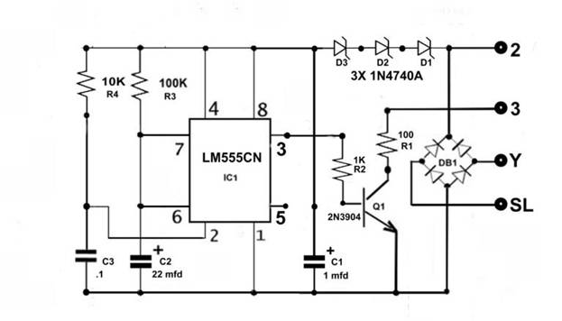
I used three 10 volt zeners in series because they are a common value; a single 30 volt zener is not. A kit of all the parts including an etched and drilled printed circuit board will be available to members of the Antique Telephone Collectors Association (ATCA).
This is a service for club members only. The cost will cover parts and shipping and be very nominal. Refer to the pictures below. Look through your junk box and find different color wires that have a spade lug crimped on one end. I`m sure you have old wiring harnesses from phone equipment that you can salvage these leads from. If the controller is going to be used in a Western Electric payphone, four different color wires each 10 inches long with a spade lug on one end are connected to the pc board output terminals 2, 3, Y, and SL You will also need a jumper 12 inches long with a spade lug on each end. You can splice together two short wires each with one spade lug. Use shrink tubing to cover the splice. Of course if you have spade lugs, wire and a crimping tool you can make the jumper the proper way. This is the L` jumper referred to later in the installation section. I`ve never done business with them but the prices seem very fair. They sell parts for single slot payphones. The coin relay and internal hopper parts for single slot Westerns are identical to the parts for the old 3 slot payphones.
Assuming you have a single coil relay and hopper in your phone I suggest you un-mount them. It`s easy to do. Remove the 3 screws accessible from the vault compartment. It will be much easier to work on and test the finished assembly if it`s sitting on your bench and not in the phone. You`ll have to make a few simple mechanical changes to the coin relay. I`ll bet the second one you modify will take you less than 5 minutes. This one will probably take a little longer. Pictures of the original coin relay are shown along-side pictures after each step in the modification.
The tools you need are: A pair of thin long-nose pliers, a small pair of diagonal wire cutters, a soldering iron, solder and a screwdriver. The first picture below is the left hand side of the unmodified coin relay. It shows the 1K resistor and three solder terminals. One of the soldered connections is the right hand wire tab` from the coil bobbin. It`s highlighted. Remove the resistor, wire jumpers and clean off the solder from the connections. Cut the wire tab` from the relay coil bobbin where it`s soldered to the lowest terminal. The second picture shows the terminals without the resistor, wire jumpers and solder. It also points out the wire tab` from the coil bobbin that was disconnected from the lowest solder terminal.
Note the black wire in the picture below. Connect a wire 1. 5 inches long between these two points. The top point didn`t have a soldered connection on it originally. You`ll have to scrape off the oxidation then tin` the metal so you`ll be able to solder to it. A close-up of the tinned edge is shown in the second picture. The other end of this black wire is soldered to the right hand terminal of the coil bobbin. Note the yellow wire. This is the jumper you made that`s 5 inches long with a spade lug on one end. Solder the bare end as shown in the picture. Refer to the picture below. It`s a close up of the back of the coin relay. The two plastic parts at the bottom are the Selector Card and the Cam. The Selector card has a permanent magnet molded into it. The Cam in conjunction with the Selector Card determined the direction of coin flow out of the hopper. Since we won`t be using this function, these parts must be modified to reduce the mechanical load and the force necessary to trigger the relay with reduced voltage.
Remove the screw that mounts the Selector Card and the Cam to the relay. There`s a nut backing up the screw - don`t loose it. I used diagonal wire cutters to nip away the plastic and filed the edge smooth. This is a comparison of an original Cam and one after modification. The cam is only being used as a spacer. It takes up the room of the shoulder` on the mounting screw. It is no longer connected to the Vane of the hopper. Use a fine pair of diagonal wire cutters to nip` away the plastic material, a hot soldering iron to melt it away from the magnet, or a file to remove the top surface of plastic. Pull out the magnet and then make the edge square and smooth. This is the Selector Card re-assembled with the modified Cam used as a spacer. The elimination of the original Cam rubbing against the Selector Card and the Vane pin inserted into the Cam have further reduced the mechanical load and the force needed to trigger the modified coin relay at reduced voltage.
This will reduce the tension the Armature Restoring Spring applies to the Rocker Arm. The Rocker Arm is the part the bottom end of the spring is attached to. This is another modification to further reduce the amount of force necessary to trigger the coin relay with reduced voltage. You will have to decide if you want the coins to return or collect. Personally I like the coins to return. Coins will always be in the return chute or pull bucket in front of you. You won`t have to run around looking for change to demonstrate your toy` to guests. Coins will also be there to answer incoming calls. Refer to the picture below. Assuming you opt for the coins to return, position the coin vane as shown. The coin vane is the blue plastic flapper`. Put a drop of glue or Scotch Tape on the edge of the flapper as shown by the arrow. Scotch Tape is a better choice if you change your mind later and want the coins to go the other way. The picture below is a side view of the coin relay. Push the armature of the relay to the energized (back) position. It should take very little force to move it smoothly all the way back. Release the armature and it should spring forward. Note the adjustment screw with the plastic cap on the end. If you manually push the armature all the way back to the energized position, the plastic cap should just touch and slightly push the surface of the flat push back spring.
This is an adjustment that can be changed by turning the screw in or out. Its function is to apply enough opposing force to overcome any residual magnetism built up by the armature, causing it to stick in the energized position after the on hook voltage is removed from the relay coil. This probably won`t happen because the original setting of the screw is usually perfect. If it does, a slight clockwise turn of the screw (a few degrees) will solve the problem. The original purpose of this adjustment was timing of the slow release function of the armature, caused by the decay of the magnetic flux, after the relay coil had been shorted by internal contacts in the coin relay.
It`s interesting that although the theory of operation of the modified coin relay is totally different than its original design, the function of these parts is exactly the same, but for a completely different reason. Testing the coin relay/ hopper assembly is simple. You will need a modular phone cord with spade ends, an ohmmeter, a phone on a working line and the ability to plug the modular cord into that line while the phone is in use.
You will also need a nickel. See below. The two clip leads on terminals 1 and G go to the test leads of the ohmmeter. Coincidently they also happened to be red and green. Unfortunately, those were the only color clip leads I had that weren`t being used for other purposes. 1- Push the armature all the way back and release it. This will force the thin plastic Coin Trigger to flip up. The ohmmeter should now show an open circuit. 4- Drop the nickel into the top of the hopper making sure it hits and pushes the plastic Coin Trigger to the down position.
The ohmmeter should now show a short circuit. 5- Hang up the phone. The coin relay should snap closed and stay that way. The nickel should get tossed out of the side of the hopper. That is if you set the hopper to return coins. The ohmmeter should still show a short circuit 6- Unplug the modular cord connected to the coin relay from the phone line. The coin relay should de-energize and the ohmmeter should now show an open circuit. Now try these tests with a bunch of quarters dropped into the hopper. Hang up the phone and watch the quarters go flying. If you set the coins to collect, the quarters will be stacked in a neat pile under the hopper. Besides being amusing, there`s another reason for doing this. The factory specification of the single coil coin relay is the capability of holding the weight of 20 quarters on the Trap Lever of the hopper and then being able to dump that weight when the Trap Lever is released.
You won`t be making $5. 00 phone calls but it`s interesting to see if your modified coin relay can still meet the original spec. Assuming these tests were successful, the next step is to install the coin relay/ hopper and the completed controller board in your payphone.
Refer to the picture below. You must start with a working Western or Northern Electric payphone. It should have a subset or some sort of network wired to it, if that particular model phone requires one. 4- The jumper on terminal L is new with a spade lug on each end. It`s 12 inches long. The other end of this jumper is connected to the coin relay. This is the jumper you made that was mentioned in the section on attaching the wires to the pc board.
It is possible to hide the controller behind the terminal board at the top of the phone with the T, TR, and L screws, or in back of the hopper. You might want to install the pc board this way if you don`t want to change the original look` of the phone.
You will have to mount some of the parts on the pc board at a right angle instead of standing up, so the finished board will be thinner. One of the most useful tools you can build if you work on Western Electric payphones is a set of jumper wires 2 feet long with spade lugs on both ends.
There are 5 transfer contacts between the top and bottom of the payphone. Unless you have x-ray vision it`s impossible to know what`s going on inside the phone when it`s locked up. 🔗 External reference
Related Circuits

When switches SW1, SW2, or SW3 are open, the input sensitivity is optimized for high-output devices such as CD players, tuners, tape recorders, iPods, miniDisc players, and computer audio outputs. The 750 Ohm value for resistors R3, R13, and...
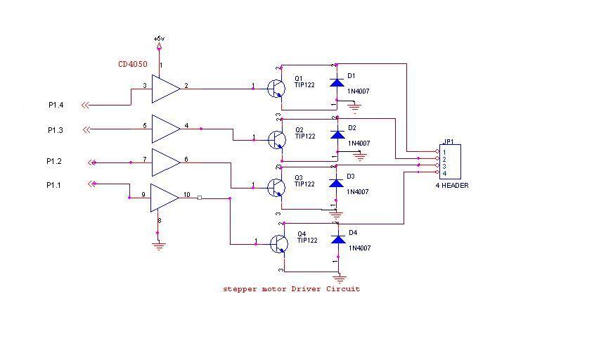
A 6V, 2A stepper motor is utilized in this circuit. The CD4050 hex buffer is employed to connect to the microcontroller. The output of the CD4050 is linked to the base of a TIP122 transistor. The emitter and collector...
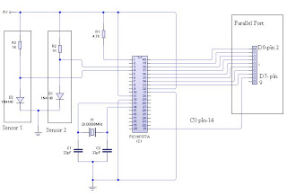
The dual-channel thermometer is a simple project based on a PIC microcontroller with ADC capabilities. It is an inexpensive thermometer that utilizes low-cost components and does not require high-sensitivity or expensive sensors. Instead, it employs a simple silicon diode...
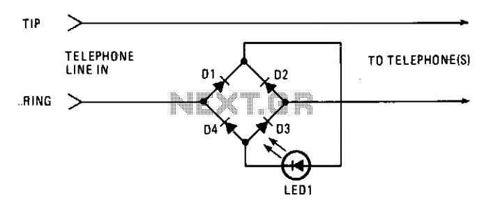
This circuit operates as a line-current sensor and can be connected in series with any of the phone lines. To indicate an "in use" status for all phones on a single line, it must be connected in series with...
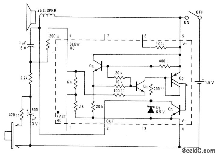
A low-drain circuit powered by a 1.5-V cell utilizes the National LM3909 flasher IC to simulate a fire-alarm siren. Pressing a button generates a rapidly increasing wail, with the tone decreasing in frequency once the button is released. The...
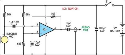
A wife was working on a doctoral dissertation that involved fieldwork, specifically personal interviews in various settings. The challenge was to find a suitable technical solution for recording these interviews. Passing a tape recorder or microphone back and forth...