
Telephone in-use indicator
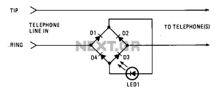
The line-current sensor circuit is designed to monitor the current flowing through a telephone line, allowing it to detect when the line is in use. The circuit typically includes a current sensing element, such as a shunt resistor or a Hall effect sensor, which generates a voltage proportional to the line current. This voltage is then processed by a comparator or microcontroller to determine the status of the line.
To ensure proper functionality, the circuit must be connected in series with the telephone line. This means that the circuit is placed before all phones on the line, allowing it to sense the current drawn when any phone goes off-hook. When the current exceeds a certain threshold, indicating that a phone is in use, the circuit can activate an indicator, such as an LED or a relay, to signal that the line is occupied.
The power supply for this circuit is derived from the telephone line itself, which typically provides a nominal voltage of around 48 volts DC when idle. This voltage is sufficient to power the circuit without requiring an external power source. The inclusion of an off-hook indicator at each phone can enhance the usability of the system, providing a local visual cue that the line is currently in use.
In summary, this line-current sensor circuit is a practical solution for monitoring telephone line usage and can be effectively implemented in both residential and commercial applications to improve communication management.This circuit functions as a line-current sensor and can be connected in series with either of the phone lines. For the circuit to indicate an "in use" status for all phones on a single line, it must be connected in series with the phone line before, or ahead of all phones on the line.
Since the power for the circuit is supplied by the phone company, a circuit could be added to each phone as an off-hook indicator. 🔗 External reference
Related Circuits

This simple circuit can monitor the overflow of water from the overhead tank. The sensor placed close to the lid of the overhead tank continuously monitors the presence of water. The described circuit functions as a water overflow monitoring system...
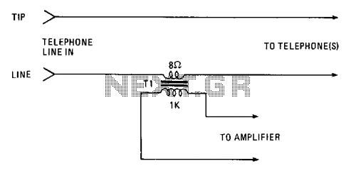
Amplify or record a telephone call using the simple circuit illustrated. The 8-ohm secondary winding of a miniature transistor output transformer is connected in series with one of the telephone lines. The 1000-ohm primary winding can be used to...
This FM spy telephone circuit is connected in series with the phone line. When there is a signal on the wires, this transmitter will radiate airwaves through the wires, which act as an antenna. There is no need for...

This circuit was utilized with an audio power amplifier to identify the point at which the output is -3 dB from maximum, indicated by LED D5, and at clipping, shown by LED D6. The indicator can be employed with...
This circuit is designed to indicate the power output level of any audio amplifier. It is simple, portable, and displays three power levels that can be adjusted to any desired value. The circuit operates by measuring the output voltage from...
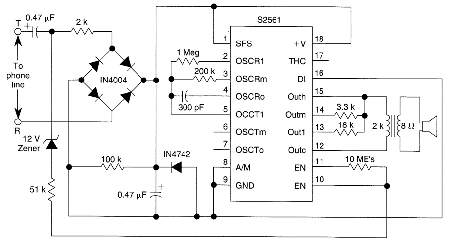
This telephone ringer utilizes an AMI chip with part number S2561 and can be powered directly from the telephone line. The audio output is approximately 50 mW when supplied with a 10-V source. The circuit design of the telephone ringer...
Warning: include(partials/cookie-banner.php): Failed to open stream: Permission denied in /var/www/html/nextgr/view-circuit.php on line 713
Warning: include(): Failed opening 'partials/cookie-banner.php' for inclusion (include_path='.:/usr/share/php') in /var/www/html/nextgr/view-circuit.php on line 713