
A simple way of phase locking microwave local oscillators
The described circuit utilizes a combination of overtone crystal oscillators and multipliers to generate local oscillator frequencies suitable for microwave applications. The design emphasizes the use of a 10 MHz reference signal, which facilitates the derivation of various comparison frequencies through logic divider chips. The high common factor (HCF) derived from the LO and reference frequencies plays a crucial role in establishing the PLL's comparison frequency, ensuring that all operational frequencies remain above 200 kHz, thus allowing for robust PLL performance.
The implementation of a sampling phase detector within the circuit enables the integration of frequency multiplication and phase detection, streamlining the design process. By applying sharp pulses generated from a varactor diode to a balanced mixer, the circuit can effectively lock the VCO to the desired reference frequency. The design also addresses potential challenges related to harmonic locking by constraining the tuning range of the VCO, which is particularly advantageous when working with lower frequencies and VCXOs.
Furthermore, the use of operational amplifiers to amplify the low-level output from the phase detector ensures adequate drive power is available for the circuit's subsequent stages. The programmable R divider enhances flexibility, allowing for precise frequency adjustments to meet specific application requirements. Overall, this circuit exemplifies a sophisticated approach to microwave frequency generation and phase locking, suitable for various electronic applications.The circuit is presented as a starting point - there will be some experimentation needed for each individual case. For the popular microwave bands the LOs are usually generated from overtone crystal oscillators followed by multipliers, with the following table showing the usual LO frequencies for the narrowband segments along with the associated crystal frequency.
The final columns show the highest frequency that is a submultiple of both this and a 10MHz reference, the highest common factor or HCF, and the associated division. This HCF can become the comparison frequency in a phase locked loop, and is the highest frequency that is possible here.
All the comparison frequencies can be derived from a 10MHz reference by making use of simple logic divider chips to give the divide by R function (all could be derived from 2MHz in fact) All the comparison frequencies are over 200kHz, so phase locked loops can be made with wide loop bandwidths. For those marked with a *, an even higher comparison frequency is possible, but the values stated keep the frequencies within a narrower band for a common design.
So now the only difficulty is providing the divide by N from the crystal frequency. An off the shelf synthesiser chip such as the MC145170, or those from other manufacturers, would make an easy job of this but there is an even simpler solution providing you are prepared to do a bit more adjustment and optimisation. Anyone who has studied the brick` range of microwave sources will have seen how a high Q cavity oscillator is locked to a reference oscillator in the 100MHz region by a sampling phase detector.
This device combines the functions of frequency multiplier and phase in one network. In the bricks, a snap varactor diode is hit with about 200mW of reference signal and so generates sharp sub-nanosecond pulses at this rate. These pulses are applied across a pair of microwave diodes, forming one input to a single balanced mixer whose other RF ports is fed with a portion of the cavity oscillator signal picked off via a small probe.
This sampling mixer approach to PLL design makes for considerable simplicity as it inherently removes any need for a high frequency divide by N circuit - but has two major drawbacks. Firstly, the VCO can lock to ANY harmonic of the reference, and in the brick designs this is prevented by restricting the electrical tuning range of the VCO to less than half of the comparison frequency - sometimes a pull in range of only 5 - 10MHz (at the fundamental L-Band frequency) can be observed.
Secondly, the output from the phase detector is at a very low level - typically a few tens of millivolts per radian rather than the 1. 6V/radian of normal logic. In effect, the complete voltage range that would have been possible for the drive power is having to be shared over every one of the comb frequencies.
However, a low noise op-amp can easily provide DC gains of the hundred or so required here, and differential amp doing this job inside the bricks is clearly visible when the side cover is removed. So, lets try this idea at lower frequencies to lock a VCXO - the very restricted tuning range of crystal oscillators means that drawback 1 is not an issue.
Look at the circuit of Figure 1, a two chip R divider (programmable for any value from 1 to 256) generates the reference. This is applied to an impulse generator using the propagation delay inherent in three high speed logic gates plus an addit
🔗 External reference
Related Circuits
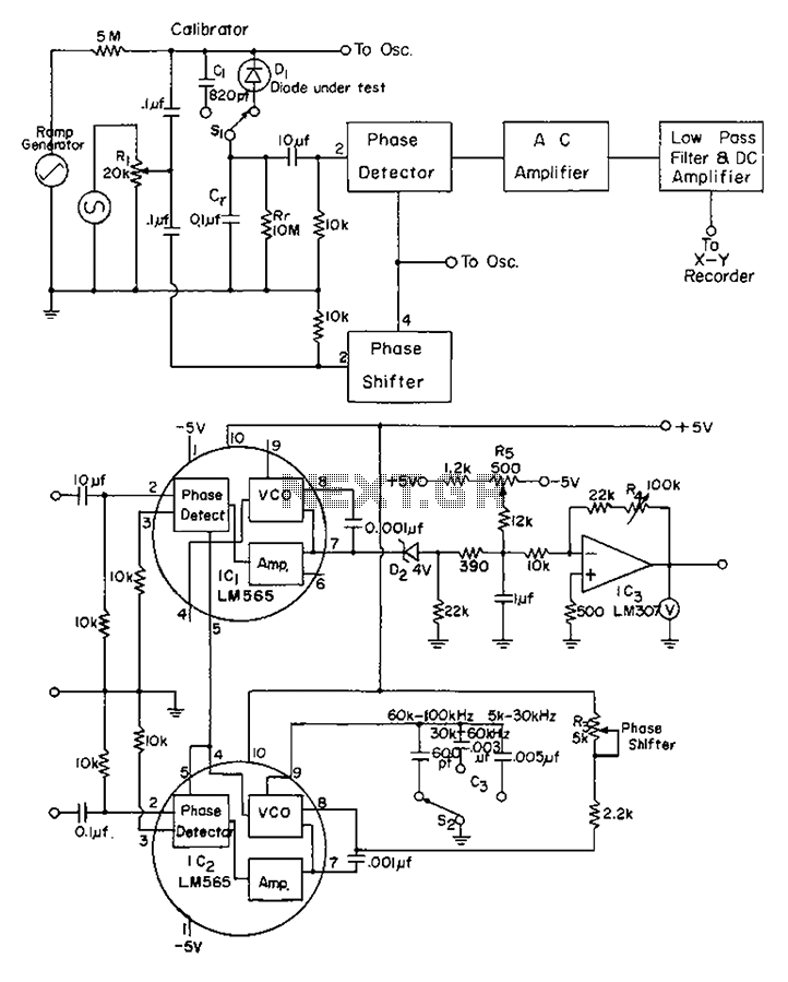
The application of automatic plotters for measuring the capacitance-voltage characteristics of solar Schottky gate diodes is discussed. A diode is connected as illustrated below. The integrated circuit (IC) generates a square wave output phase. Additionally, resistor R3 can be...
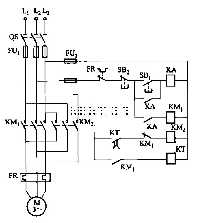
The circuit illustrated in Figure 3-127 utilizes a time relay (KT) in place of a speed relay. The timing duration is adjustable and typically set between 1 to 2 seconds. This circuit is designed to operate effectively in dusty...
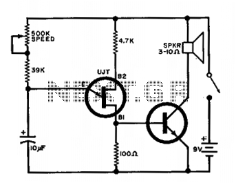
The output of the UJT oscillator is connected to a general-purpose NPN transistor, which drives the speaker. The oscillator's frequency can be adjusted from 15 to 240 beats per minute. The UJT (Uni-Junction Transistor) oscillator is a relaxation oscillator that...
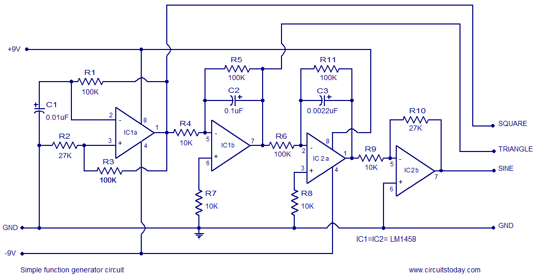
A simple function generator circuit utilizing the LM1458 is presented here. The LM1458 is a dual general-purpose operational amplifier. The two op-amps within the LM1458 share a common bias network and power supply line, yet operate independently. The function generator...

The two most common motor control methods are DC Chopper control and Phase Angle control. This article explores the differences between the two methods, identifying some key trade-offs that can be useful for motor control designers when determining the...
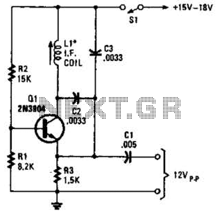
A simple oscillator for intermediate frequency (IF) alignment at 455 kHz can be useful in field testing or in scenarios where a standard signal generator is available. The inductor (L1) should resonate at the desired output frequency with the...