
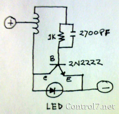
Simple Rf Test Oscillator Circuit

The oscillator circuit is designed to generate a stable sine wave signal at 455 kHz, commonly used in radio frequency applications, particularly for IF alignment in superheterodyne receivers. The circuit typically consists of an inductor (L1) and two capacitors (C2 and C3) configured in a tank circuit that determines the resonant frequency.
The resonant frequency (f) of the LC circuit can be calculated using the formula:
f = 1 / (2π√(L * C))
where L is the inductance in henries and C is the total capacitance in farads. In this case, the total capacitance (C) is the series combination of C2 and C3, which can be calculated as:
1/C = 1/C2 + 1/C3
This configuration allows for fine-tuning the output frequency by adjusting the values of the capacitors. The oscillator can be powered by a low-voltage DC source, and it may include additional components such as resistors for biasing or feedback to stabilize the oscillation.
The output can be taken directly across the inductor or through a buffer stage to prevent loading effects that could alter the frequency. This oscillator can be employed in various applications, including signal generation for testing receivers, frequency calibration, and alignment procedures, making it a valuable tool for engineers and technicians in the field of electronics. A simple oscillator for IF alignment (455 kHz) can prove useful in field testing or where a standard signal generator is available. LI should resonate at the desired output frequency with the series combination of C2 and C3. 🔗 External reference
Related Circuits
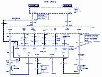
The section of the 1996 Ford Windstar wiring diagram includes details on power distribution, common connections, rear circuits, ignition systems, the fuse panel, battery connections, instrument illumination, radio wiring, left rear speaker connections, remote headphone module, solid-state components, and...

This circuit responds to the presence of any conductive object, including humans. It does not detect object movement but can function as a proximity sensor. The circuit operates on the principle of capacitive sensing, utilizing a capacitor to detect changes...

This circuit diagram for a logic tutor kit was created using MS Word graphics. While modern software is commonly utilized, there may be instances where traditional methods are necessary. Employ a sharp pencil and a ruler to ensure precision;...

Figure 2-33 (a) illustrates the schematic diagram of a robot approaching an object. When no objects are detected in front of the robot, it moves forward in a straight line. If an object is detected on the left or...
The LED is a fascinating component for amateur electronics hobbyists. The primary characteristic of an LED is that it requires a minimum of 3 volts to illuminate. Various circuits have been discovered to drive an LED using a single...

This signal generator uses a three channel DAC to generate Composite video signal (CVBS) and S video signal (Y/C separated) at the same time, left one channel is not used in NTSC format. It is assigned for one of...
Warning: include(partials/cookie-banner.php): Failed to open stream: Permission denied in /var/www/html/nextgr/view-circuit.php on line 713
Warning: include(): Failed opening 'partials/cookie-banner.php' for inclusion (include_path='.:/usr/share/php') in /var/www/html/nextgr/view-circuit.php on line 713