
A tube amplifier 01 HI-FI
The circuit described operates within a power supply system designed for aircraft applications, where reliability and performance are critical. The output transformer’s frequency response is particularly notable for its low distortion across the specified range, which is essential for audio and signal integrity in high-fidelity applications. The rectifier bridges, constructed from 1N4007 diodes, are robust components capable of handling high reverse voltages, ensuring that the system can operate under various load conditions without failure.
The configuration of resistors and capacitors plays a vital role in maintaining voltage stability and preventing overshoot during transient conditions. The use of a Darlington pair (VT1 and VT2) provides a high current gain, allowing the circuit to drive loads more effectively while maintaining a stable output voltage. The choice of high-voltage transistors (2SC3306 and 2SC3743) indicates that the circuit is designed to handle significant power levels, making it suitable for demanding applications.
The filtering capacitors (C7 and C9) are strategically placed to mitigate high-frequency noise that could interfere with the performance of the power supply. This noise filtering is crucial in sensitive electronic environments, such as those found in aircraft systems, where electromagnetic interference can adversely affect operation.
Overall, the circuit exemplifies advanced engineering practices, utilizing high-quality components and thoughtful design to achieve a reliable and efficient power supply solution for aviation applications.As a result of high quality materials and advanced technology, the machine output transformer frequency response can reach 10Hz (a 0.8dB) ~ 50Hz (a ldB), to improve the overall index basis. Aircraft power supply voltage section shown in Figure 1-42 in each group, three rectifier bridges are constituted by the four 1N4007, Rl ,. R2 is Cl, C2. C3 and C4 are resistors, two capacitors connected in series in order to prevent Because a partial pressure caused by uneven overvoltage.
Following is used to achieve high-voltage electrical delay control, the machine uses its normally open contact groups. R3 is power resistors, since the relay Kl output between the output and the VT1 have 500v - 360V-140V pressure, so affixed R3 to reduce the requirements for VT1 tube, R3 take 60V (40mA a R4 taken 82kn C6 take lO fiF.
It used to reduce grain output .VD13 ~ VD15 crossing the regulator diode, electrical voltage to around 360V o VT1, VT2 connected in Darlington form, to get a better voltage regulation review C7 and C9 filter high frequency wave capacitors, and R3 taken o.lrdrFpR5 like to share power, R5 taken 1.5kfl.R6 take 82kfl + C7 with R4 a C 5.VT1, VT2 uses high-voltage power transistor 2SC3306, VT3 as the power transistor 2SC3743
Related Circuits
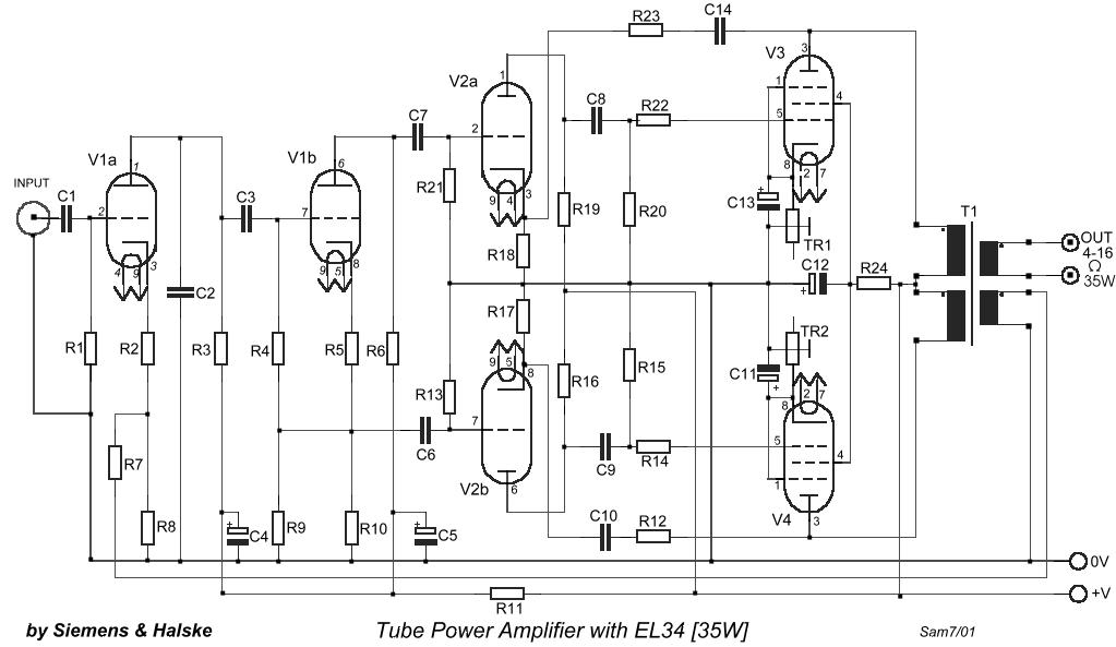
The circuit is designed to create a power amplifier that utilizes E80CC and EL34 vacuum tubes to achieve optimal performance, providing an output of 35 Watts. The power amplifier circuit employs E80CC and EL34 vacuum tubes, which are known for...
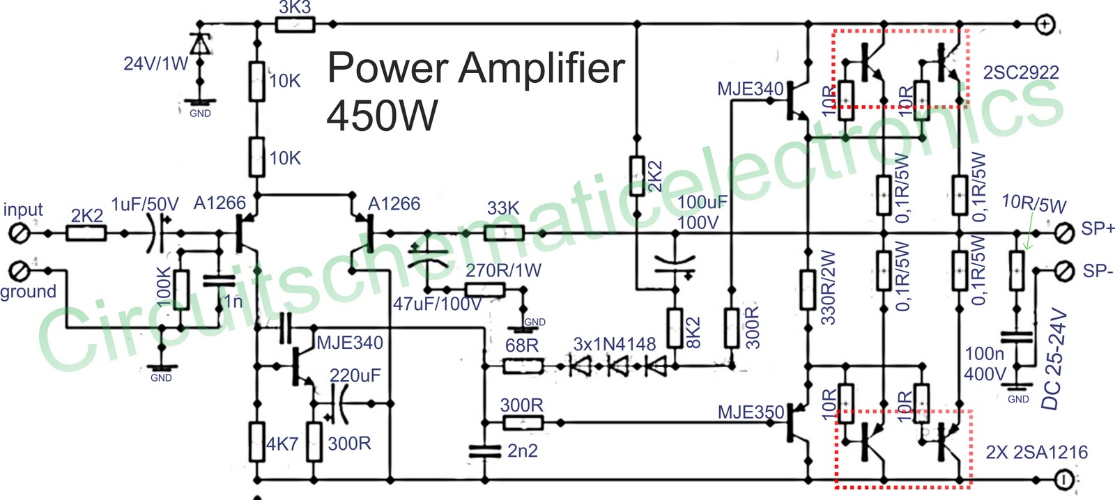
Below is a circuit of power amplifiers with a power output of 450 watts in mono mode. These amplifiers are frequently utilized in high-power applications, suitable for events, and designed for enclosed spaces. This amplifier is appropriate for woofers...
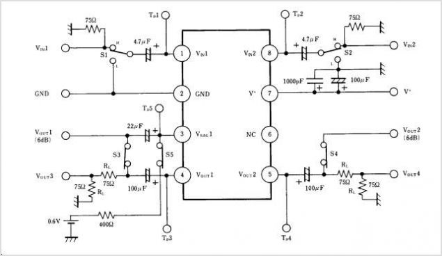
NJM2274AR is a sub-package of NJM2274A. For a detailed description, please refer to NJM2274A. The datasheet for NJM2274AR can be downloaded from the link below. Manufactured by New Japan Radio Co., Ltd. The NJM2274AR is a component that serves as...

A compact audio amplifier circuit utilizing the TDA 7052 integrated circuit from Philips. This circuit is suitable for use as a pocket radio amplifier, delivering an output power of 2 watts. The TDA 7052 is a low-voltage audio amplifier designed...
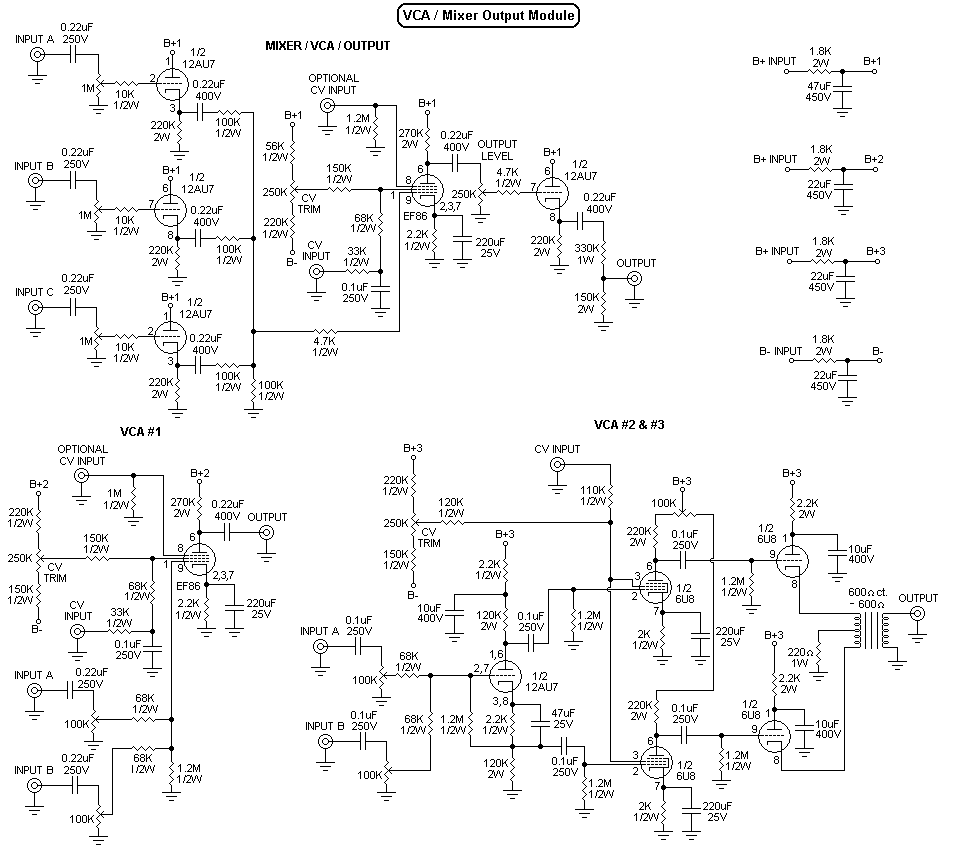
Recently, a music synthesizer has been constructed using vacuum tubes. Although designed primarily as a percussion synthesizer, it can also be controlled via a keyboard or a MIDI to CV converter. The initial module developed is a dual voltage-controlled...
The AN41240A is a single-chip integrated circuit (IC) designed for audio applications. It employs a single-hall-sensor drive on the input side of the spindle motor drive block and utilizes a low-noise direct PWM drive of sine wave on the...