
450w audio power amplifier circuit
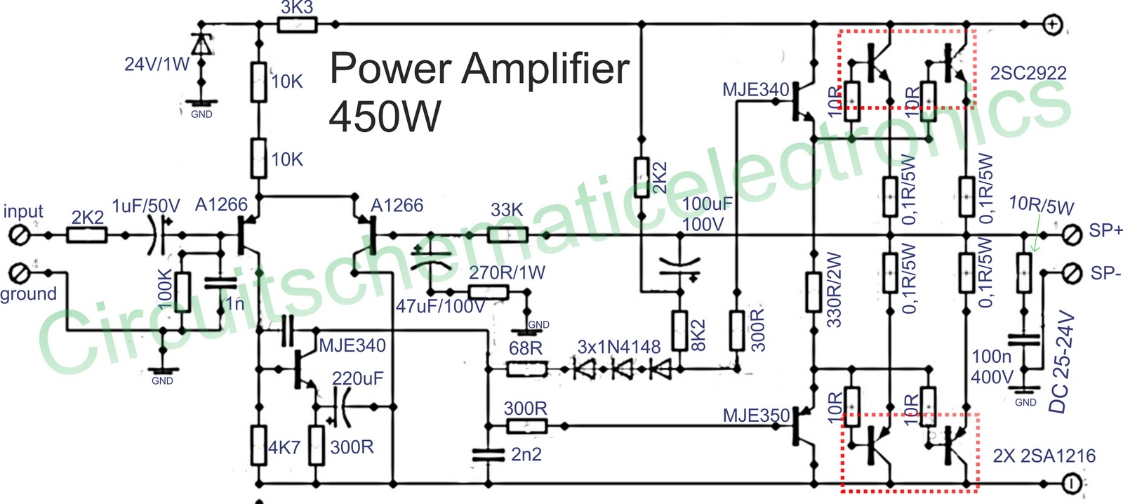
The circuit design described involves a robust power amplifier capable of delivering 450 watts in mono configuration, making it suitable for high-demand audio applications. The amplifier is designed to handle the rigorous requirements of live events and enclosed spaces, where sound projection and fidelity are critical.
This amplifier circuit is optimized for use with woofers and full-range speakers, with the capability to be configured for subwoofers, enhancing the overall audio experience. The choice of components is crucial for achieving optimal performance. The power supply circuit is particularly important, as it must be designed to provide stable and adequate voltage levels to the amplifier.
Electrolytic capacitors play a significant role in the power supply, and selecting capacitors with a voltage rating of at least 80V and a capacitance of 20,000µF or higher is essential. This configuration helps to ensure that the power supply can handle high transient currents without significant voltage drops, especially during demanding bass output, which is common in high-power audio applications.
The diode bridge is another critical component, with a recommended minimum rating of 35A. This component is responsible for converting the AC voltage from the transformer into DC voltage for the amplifier. Proper sizing of the diode bridge is necessary to prevent overheating and failure during operation. Additionally, adjustments to the current input voltage may be made to accommodate different operating conditions or to optimize performance further.
In conclusion, the design of this 450-watt mono power amplifier circuit emphasizes the importance of a well-engineered power supply to ensure reliable and high-quality audio output. The careful selection of capacitors and diode bridges contributes to the amplifier's ability to perform under demanding conditions, making it suitable for various high-power audio applications.Below it is a circuit of power amplifiers with power output of 450 watts mono, amplifiers are also frequently used in the amplifier a high-power amplifier, which used in an event, in the field and the placed closed. Because this amplifier suitable for the woofer, fullrange speaker, and can also be fixed for the subwoofer speaker.
To further stren gthen and maximize the amplifier, its power supply circuit also must be accurate, for electrolytic capacitors in power supply, voltage capacitors use 80V or more, and a capcity 20000uF upwards, so when the bass amplifier is high, the voltage is not lot of experience dropping. Diode bridge use a minimum of 35A, or adjust the current input voltage. If the power supply has fulfilled the desire, the supply to the power amplifier. 🔗 External reference
Related Circuits
The preamplifier is safeguarded against excessive input signals of either polarity by utilizing the 2N5909 junction field-effect transistor. A nulling circuit allows for the adjustment of the preamplifier output voltage to zero at a fixed low level (up to...
A simple low voltage/current power supply that can accept a wide range of input voltages, up to several hundred volts. The input range is specified as 20 to 160V DC, with an output requirement of 10V and a maximum...
Operating at approximately 1.1 GHz, the detector senses disturbances in the electromagnetic field surrounding the antenna. The Doppler signal generated by detector D1 is amplified and used to control a power MOSFET switch. The antenna consists of a short...
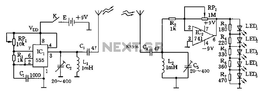
The circuit diagram of the device features a 555 timer IC configured as a transmitter and a receiver, divided into two sections. The 555 timer in the transmitter section serves as the core component of a frequency oscillator. The...
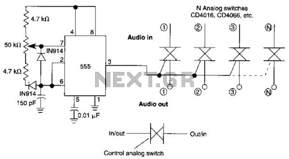
A 555 timer can be configured to simulate a multi-gang potentiometer by controlling the mark-space ratio. The switching rate should be at least twice the maximum expected signal frequency that the potentiometer has to handle. The 555 timer is an...
This application note describes the evaluation board for the AD7892-2, a 12-bit analog-to-digital (A/D) converter. The AD7892-2 is a high-speed, low-power device capable of 500 ksps sampling rate, operating from a single +5V supply. It features an on-chip track/hold...
Warning: include(partials/cookie-banner.php): Failed to open stream: Permission denied in /var/www/html/nextgr/view-circuit.php on line 713
Warning: include(): Failed opening 'partials/cookie-banner.php' for inclusion (include_path='.:/usr/share/php') in /var/www/html/nextgr/view-circuit.php on line 713