
A Very Useful Timed Beeper Circuit Schematic
This circuit employs a timer integrated circuit (IC) such as the 555 timer or a similar timing chip configured in astable or monostable mode. The choice of R3 and C1 is critical as these components define the timing interval, with their values directly influencing the frequency of oscillation. The flashing LED (D2) serves as a visual indicator of the circuit's operational status, allowing users to confirm that the timer is functioning correctly. The operational amplifiers (IC1A and IC1B) are configured to drive the LED and can be used to amplify the signal from the timing circuit.
The piezo sounder, activated through transistor Q1, provides an auditory alert, enhancing the functionality of the circuit for various applications. The circuit's design allows for flexibility in timing adjustments via SW1, which can be configured to select different timing intervals based on user requirements. The reset mechanism, while not instantaneous, ensures that the timing can be effectively controlled, and the option to bypass the switch for a fixed duration simplifies the design for specific applications.
Overall, this alerting circuit is versatile and can be adapted for various timing needs, making it suitable for educational, recreational, and household applications. Proper selection of components and careful consideration of circuit behavior during reset operations are essential for optimal performance.This circuit is intended for alerting purposes after a certain time is elapsed. It is suitable for table games requiring a fixed time to answer a question, or to move a piece etc. In this view it is a modern substitute for the old sandglass. Useful also for time control when children are brushing teeth (at least two minutes!), or in the kitchen, a nd so on. Pushing on P1 resets IC2 that start oscillating at a frequency fixed by R3 & C1. With values shown, this frequency is around 4Hz. LED D2, driven by IC1A & B, flashing at the same oscillator frequency, will signal proper circuit operation. SW1 selects the appropriate pin of IC2 to adjust timing duration: When the selected pin of IC2 goes high, IC1C drives Q1 and the piezo sounder beeps intermittently at the same frequency of the LED.
After around 7. 5 seconds pin 4 of IC2 goes high and IC1D stops the oscillator through D1. If you want to stop counting in advance, push on P2. SW1 can be any type of switch with the desired number of ways. If you want a single fixed timing duration, omit the switch and connect pins 9 & 13 of IC1 to the suitable pin of IC2. The circuit`s reset is not immediate. Pushing P2 forces IC2 to oscillate very fast, but it takes some seconds to terminate the counting, especially if a high timer delay was chosen and the pushbutton is operated when the circuit was just starting.
In order to speed the reset, try lowering the value of R5, but pay attention: too low a value can stop oscillation. 🔗 External reference
Related Circuits
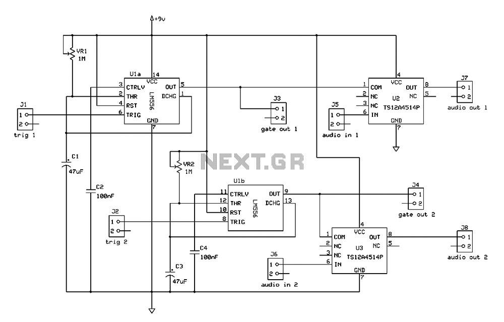
The Switchgate is a simple dual gate circuit based on a 556 timer configured in monostable mode, featuring a trigger input that activates two switches. The outputs of the monostables are also available individually. Recent research has led to...
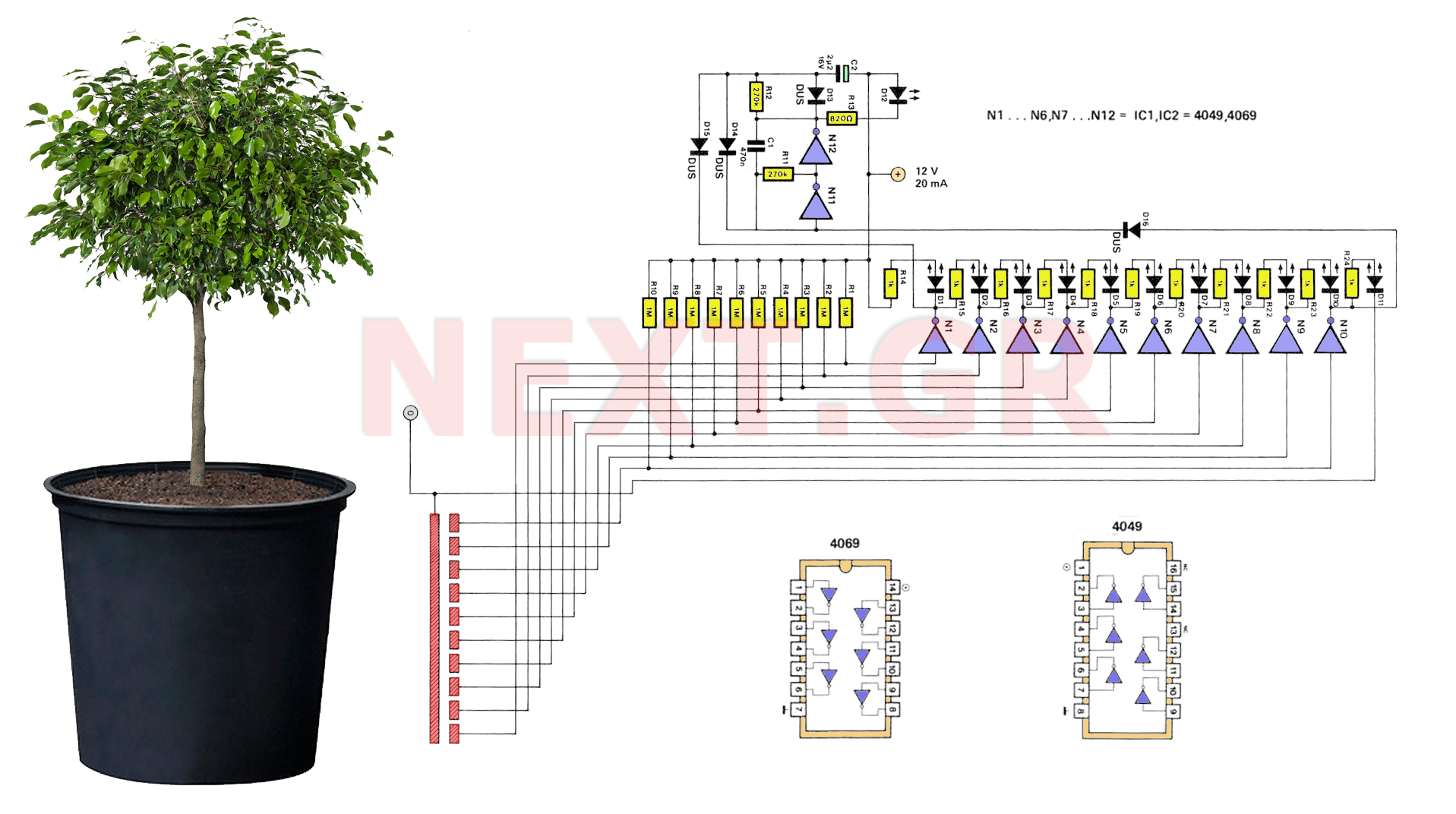
A series of LEDs is used to alert the gardener when plants require watering. By utilizing two conventional digital integrated LEDs along with a series of additional LEDs, this device serves as a practical tool for gardening. It detects...
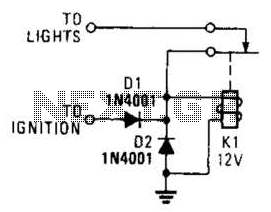
A relay and two diodes are all that is needed; the relay performs the job of a buzzer, so no annunciator is required. When the lights are left on while the ignition is off, the normally closed relay contacts...
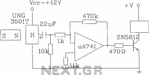
The UGN-3501T Hall sensor features a highly sensitive counter circuit diagram, allowing it to detect very small changes in magnetic fields. This capability enables the detection of ferrous metals. Utilizing this characteristic, it can be employed to count loads....
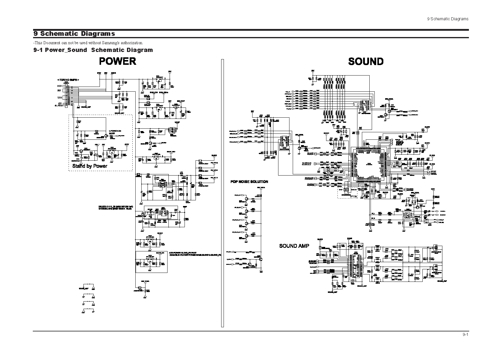
Samsung C3330 Circuit Diagram Download Manual PDF Download. The Samsung C3330 circuit diagram serves as a comprehensive reference for understanding the electronic architecture of the device. This schematic provides detailed insights into the interconnections between various components, including the microcontroller,...
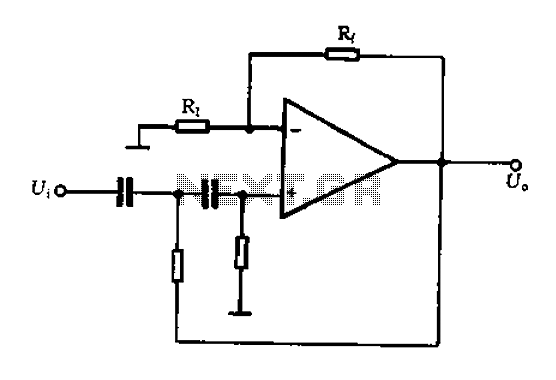
A typical two high-pass filter circuit. A high-pass filter (HPF) is an electronic circuit that allows signals with a frequency higher than a certain cutoff frequency to pass through while attenuating signals with frequencies lower than the cutoff frequency. A...
Warning: include(partials/cookie-banner.php): Failed to open stream: Permission denied in /var/www/html/nextgr/view-circuit.php on line 713
Warning: include(): Failed opening 'partials/cookie-banner.php' for inclusion (include_path='.:/usr/share/php') in /var/www/html/nextgr/view-circuit.php on line 713