
UGN-3501T counter circuit diagram of a Hall sensor

The UGN-3501T Hall sensor operates on the principle of detecting magnetic fields, which is essential for various applications such as proximity sensing and load counting. The sensor's high sensitivity allows it to respond to minimal variations in magnetic flux density, making it suitable for environments where precise detection of ferrous materials is required.
In the described circuit, the output from the UGN-3501T generates a 20 mV peak pulse when a magnetic field, such as that produced by a moving ferrous object (e.g., a ball), is detected. This pulse is a direct result of the Hall effect, where the sensor generates a voltage proportional to the magnetic field strength. To ensure that this signal can effectively control other components, it is necessary to amplify it.
The operational amplifier (A741) serves this purpose by increasing the voltage level of the pulse. The A741 is a versatile op-amp, known for its reliability and performance in signal amplification tasks. Following amplification, the signal is sent to a 2N5812 transistor, which acts as a switch. The transistor allows for the control of higher power loads based on the low-power signal received from the op-amp.
The use of a 2N5812 transistor is advantageous due to its ability to handle higher currents and voltages, making it suitable for driving output devices such as counters or relays. The output terminal connected to the counter can register each pulse generated by the Hall sensor, enabling accurate counting of the objects passing over the sensor's detection zone.
Overall, the integration of the UGN-3501T Hall sensor with the A741 op-amp and 2N5812 transistor presents a robust solution for applications requiring precise detection and counting of ferrous materials in a variety of industrial and commercial settings. This configuration can be further expanded or modified to suit specific operational requirements, enhancing its versatility in electronic design.UGN-3501T Hall sensor due to the composition of the counter circuit diagram UGN-3501T has a high sensitivity, it can feel very small magnetic field changes. Thereby detecting the presence of ferrous metals. We use this characteristic can be made it count loading. When the ball rolled over the position of Hall sensor, the sensor outputs a peak pulse 20mV. After this pulse signal is amplified to drive the op amp A741 2N5812 transistor, so as to complete the on-off process. The counter is connected to the output terminal can constitute a 2N5812 counter.
Related Circuits

This schematic is directly sourced from the Altera ByteBlaster datasheet or manual, which provides comprehensive details regarding the connector's functionality and pin connections. It is advisable to review the datasheet available on their website or through a search engine...
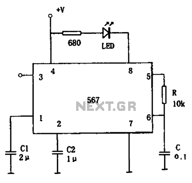
The FM demodulation circuit is illustrated in Figure 567. The FM signal is input at pin 3, and the demodulated signal is output from pin 5. The center frequency of the FM demodulation circuit is determined by the formula...
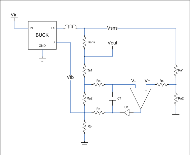
This is a cost-effective circuit that incorporates precise current limiting functionality into a voltage regulator. The circuit described is designed to enhance the performance of a voltage regulator by integrating a current limiting feature. This is particularly beneficial in applications...
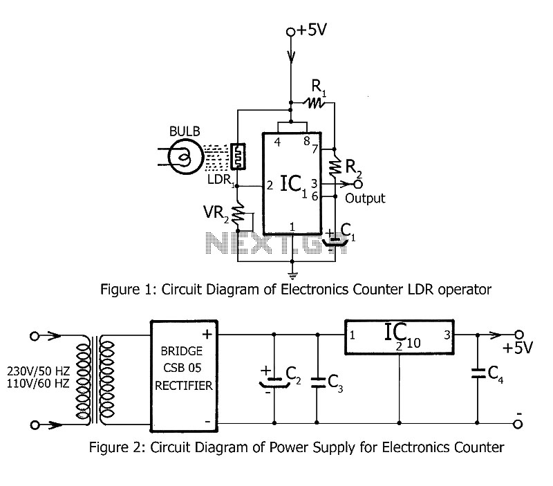
Simple counting can be performed by anyone, but counting over large intervals can be tedious and prone to errors. A previously published project, the Digital Counter, serves as a foundation for this electronics counter, which is the second project...
This circuit is a difference amplifier. It functions as an inverting amplifier that enables the subtraction of two voltages, effectively performing a summation. The difference amplifier is a fundamental circuit configuration in analog electronics, primarily used for amplifying the difference...
Another unit of graphic equalizer with five bands. The primary distinction from other circuits is the use of transistors instead of integrated circuits (ICs), and the power supply operates at +/- 24V DC, which ensures low distortion and greater...