
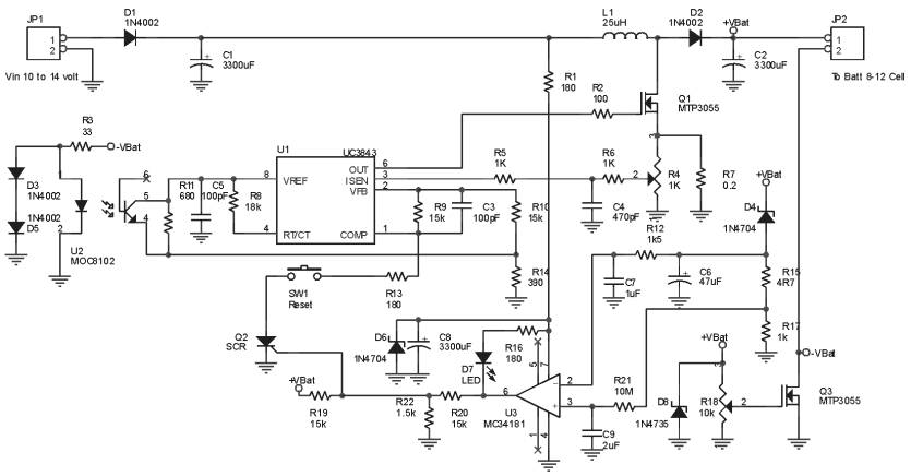
AC RMS and DC converter circuit

An AC to DC circuit typically employs components such as diodes, capacitors, and sometimes inductors to achieve the conversion. The fundamental operation begins with the rectification of the AC signal, which is most commonly performed using a bridge rectifier configuration. This arrangement consists of four diodes arranged in a bridge format, allowing for the conversion of both halves of the AC waveform into a unidirectional flow of current.
Following rectification, the output voltage is still pulsating, which necessitates the use of filtering components. Capacitors are employed to smooth the rectified output, reducing the ripple voltage and providing a more stable DC output. The selection of the capacitor value is critical; larger capacitance values yield lower ripple voltages but may increase response time to load changes.
In scenarios where the input signal deviates from a pure sinusoidal waveform, such as triangular or square waves, the circuit must account for increased distortion. The RMS (Root Mean Square) value is crucial in these instances, as it provides a measure of the effective voltage of the AC signal. The relationship between the average value and the RMS value becomes essential for accurate measurements and can introduce significant errors if not properly accounted for.
For signal measurement devices, the AC RMS value is pivotal in determining the equivalent DC output. The conversion path must ensure that the output accurately reflects the input signal's characteristics, particularly in applications where precise measurements are necessary. Therefore, careful design and component selection are paramount to minimize distortion and maximize measurement accuracy in AC to DC conversion applications.AC to DC circuit is a sinusoidal alternating current into direct current crossing the circuit, if the input signal is not sinusoidal but triangular wave or sine wave distortion is relatively large, the relationship between the average and rms on 1.11 times, thus measuring error will be relatively large, this situation do not mean, but can be obtained directly converted into AC effective value converted to DC, AC RMS circled DC power conversion path, which is mainly used for signal measurement device.
Related Circuits

The schematic includes programmable AVRs. For other members of the AVR family or additional programmable ICs compatible with Ponyprog, there is a J1 connector (CON10) that facilitates hardware expansion of the programmer. Additional information about compatible ICs can be...
This circuit utilizes a 555 timer to control a 4017 decade counter. The outputs from the counter are used to drive transistor relay drivers. The duration for which the lights remain "on" can be adjusted by modifying the connections...
This circuit when used with a 555 timer will cause light emitting diodes to turn on and off more slowly. This will make the LEDs appear similar to incandescent lamps. The described circuit utilizes a 555 timer IC configured in...
The Ultra Fast Battery Charger for Nickel-Cadmium (NiCad) battery cells is designed to efficiently charge NiCad batteries. This charger, referred to as the Ultra Fast NiCad Battery Charger, is capable of rapidly filling NiCad battery cells. The charger is...
This circuit is designed to test the servo motor of a parabolic antenna. It functions effectively, although a system with a low-noise block feed (LNBF) is generally more suitable. Many users continue to utilize systems that employ an LNB...
Build a personal data logger for recording analog signals. The MiniLOGGER provides 8-channel analog input (-99mV to +999mV), 1-channel pulse input, battery backup with 256kB SRAM, a Real-time Clock, and RS232C communication. Recording can be initiated or stopped using...