
Incandescent LED Circuit
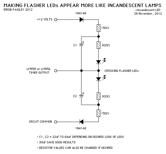
The described circuit utilizes a 555 timer IC configured in an astable mode to create a pulse-width modulation (PWM) signal that controls the brightness of light-emitting diodes (LEDs). The 555 timer operates by generating a square wave output, which can be adjusted in frequency and duty cycle through external resistors and capacitors.
In this application, the circuit is designed to simulate the gradual dimming and brightening effect characteristic of incandescent lamps, providing a more visually appealing lighting experience. The output from the 555 timer is connected to the anodes of the LEDs, while the cathodes are grounded.
To achieve the desired effect, the timing components (a resistor and a capacitor) must be selected carefully. The resistor values will influence the charge and discharge times of the capacitor, which in turn affects the frequency of the PWM signal. A larger capacitor will result in a slower charge and discharge cycle, leading to a more pronounced fading effect.
To further enhance the performance, a low-pass filter can be employed at the output to smooth out the PWM signal, reducing flicker and creating a more uniform light output. This can be achieved by adding a capacitor in parallel with the LEDs, which will help to maintain a steady current flow during the off periods of the PWM cycle.
Overall, the circuit effectively mimics the warm glow of incandescent lighting by providing a controlled and gradual change in brightness, making it suitable for applications where aesthetic lighting is desired.This circuit when used with a 555 timer will cause light emitting diodes to turn on and off more slowly. This will make the LEDs appear similar to incandescent lamps. 🔗 External reference
Related Circuits
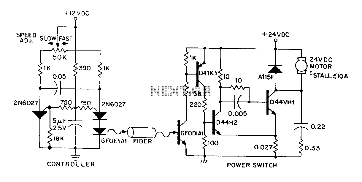
A DC power supply can be controlled through an optical fiber. The circuit includes a small DC motor (1/12 hp) that offers an isolated speed control channel. The control logic operates as an independent module, consuming 300 mW of...
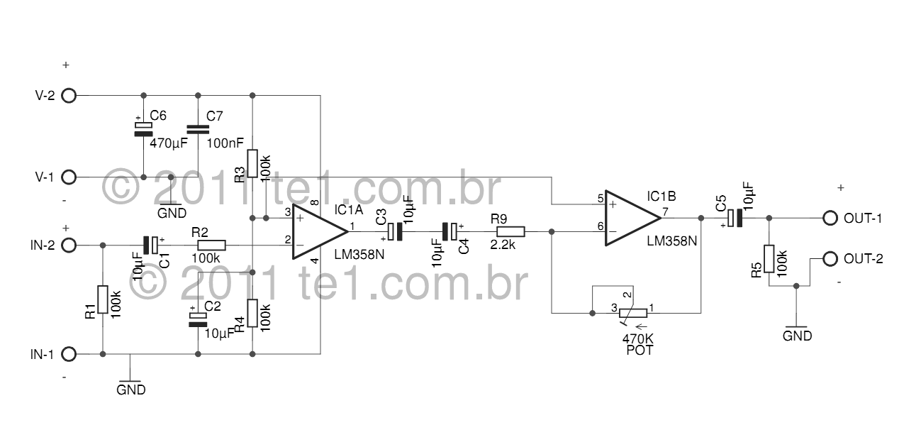
The LM358 series consists of two independent, high-gain, internally frequency-compensated operational amplifiers designed specifically to operate from a single power supply over a wide range of voltages. Operation from split power supplies is also possible, and the low power...

The objective of the circuit is to create an electronic dice using the functionality of a 555 timer integrated circuit operating in astable mode. The electronic dice circuit utilizes a 555 timer configured in astable mode to generate a series...
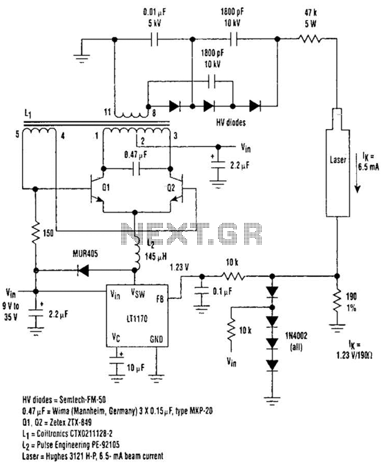
Driving Helium-Neon lasers can be greatly simplified using this power supply configuration. When power is applied, the laser does not conduct, and the voltage across the 190-ohm resistor is zero. However, a resonant circuit and a voltage tripler then...
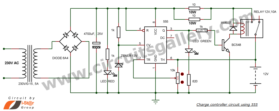
This is a simple DIY charge controller schematic created in response to a request from one of the readers on our Facebook page. The primary component of this automatic battery charger circuit is a 555 timer, which compares the...
The high-frequency signal generator is designed to produce a low frequency of 1 kHz, an intermediate frequency (IF) signal of 465 kHz, and high frequencies ranging from 525 kHz to 1605 kHz. This device is particularly useful for radio...