
Accurate Bass Tone Control

The design of this electronic tone control circuit addresses the common problems associated with traditional potentiometer-based systems. By utilizing SSM2404 selectors, the circuit achieves precise control over audio signal levels without the noise typically associated with mechanical switches. The configuration allows for a smooth transition between multiple gain settings, enhancing the listening experience by providing fine-tuning capabilities for bass frequencies. The mirroring feature of the circuit enables users to choose between boosting or cutting bass, catering to different audio preferences and environments.
The choice of a microcontroller or logic circuits to drive the selectors adds flexibility to the design, allowing for potential integration with digital control systems or remote operation. The careful selection of components, such as R9 and R12, ensures that the circuit maintains optimal performance while being safeguarded against variations in load conditions. The low output impedance is critical in preventing signal degradation, making this circuit suitable for high-fidelity audio applications.
Overall, this electronic tone control circuit represents a significant advancement over conventional systems, providing a reliable, efficient, and user-friendly solution for audio signal processing. The performance metrics, including low distortion and wide bandwidth, further validate its effectiveness in high-quality audio applications.A difficult problem in the design of conventional stereo tone controls is obtaining synchronous travel of the potentiometers. Even a slight error in synchrony can cause phase and amplitude differences between the two channels. Moreover, linear potentiometers are often used in such controls, and these give rise to unequal performance by human heari
ng. Special potentiometers that counter these difficulties are normally hard to obtain in retail shops. A good alternative is a control based on a rotary switch and a discrete potential divider. The problem with this that for good tone control more than six steps are needed, and switches for this are also not readily available. Fortunately, electronic circuits can remove these difficulties. The analogue selectors used may be driven by mechanical switches, standard logic circuit or a microcontroller.
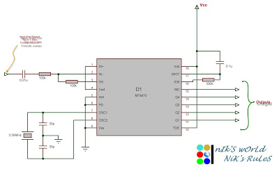
The selectors used in the present circuit are Type SSM2404 versions from Analogue Devices, which switch noiselessly. Each IC contains four selectors, so that a total of eight are used. The step size is 1. 25 dB at 20 Hz with a maximum of 10dB. The circuit can be mirrored with S1, which means that a selection may be made of amplification or attenuation of bass frequencies.
The user can choose between attenuation only and extending the range by dividing R9. The control can be bridged by switch S2. To prevent the output impedance of the circuit having too much effect on the operation of the circuit, the output impedance must be ‰¤ 10 . Resistor R1 2 protects the circuit against too small a load. At maximum bass amplification at Ui n = 1 V r. m. s. , the THD+N <0. 001% for a frequency range of 20 Hz to 20kHz and and a bandwidth of 80kHz. The circuit draws a current of about 10 mA. 🔗 External reference
Related Circuits
Connect the serial cable to the serial port. If using a USB to TTL, RS232, or serial converter, plug it into the USB port. Next, short the Tx pin to the Rx pin or the TxD pin to the...

This circuit utilizes a 74S00 Schottky TTL gate. Additionally, no inductors are necessary. The 74S00 is a dual 4-input NAND gate that operates at high speeds due to its Schottky technology, which minimizes propagation delay and power consumption. The circuit...
This project automates home appliances via a Bluetooth-enabled PC. A USB Bluetooth adapter is utilized on the PC side, while a Serial Bluetooth module is employed for communication. This project involves the integration of a Bluetooth-enabled PC with home appliances...
This circuit enables audio monitoring of a remote location, functioning as both a room monitor and a baby alarm. It can be powered by a 12-volt battery or a mains power supply. The interconnection utilizes three wires, allowing for...
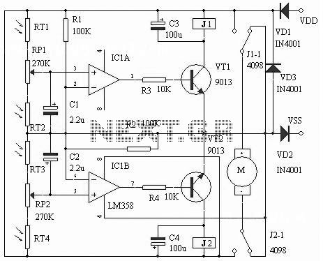
The following circuit illustrates an LM358 IC Solar Controller Circuit Diagram. Features include its application in mobile communications base stations and conversion capabilities. The LM358 IC Solar Controller Circuit utilizes the operational amplifier LM358 to regulate and manage solar energy....
In a hybrid system, an analog system with digital control, voltage-controlled components are crucial as they can be interfaced with a Digital-to-Analog Converter (DAC) from the digital system. In hybrid systems, the integration of analog and digital components allows...