
LM358 IC Solar Controller
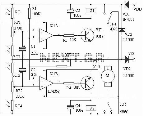
The LM358 IC Solar Controller Circuit utilizes the operational amplifier LM358 to regulate and manage solar energy. This circuit is designed to optimize the charging of batteries, ensuring efficient energy conversion from solar panels. The LM358 consists of two independent, high-gain, frequency-compensated operational amplifiers, making it suitable for various applications, including solar energy management.
In this configuration, the circuit typically includes a solar panel, a battery, and the LM358 IC. The solar panel generates voltage when exposed to sunlight, which is then fed into the non-inverting input of one of the operational amplifiers. The output of this amplifier controls a switching element, such as a MOSFET or a relay, which connects or disconnects the solar panel from the battery based on the battery's charge level.
The second amplifier in the LM358 can be used for voltage comparison, ensuring that the battery does not overcharge by disconnecting the solar panel when the battery reaches a certain voltage threshold. Additional components, such as resistors and capacitors, are included to set the reference voltage levels and to filter any noise that may affect the operation of the circuit.
This solar controller circuit is particularly beneficial for mobile communication base stations, where reliable and efficient power management is crucial. It can also be adapted for various other applications that require solar energy conversion, making it a versatile solution for renewable energy systems.The following circuit shows about LM358 IC Solar Controller Circuit Diagram. Features: also as a mobile communications base stations, convert .. 🔗 External reference
Related Circuits
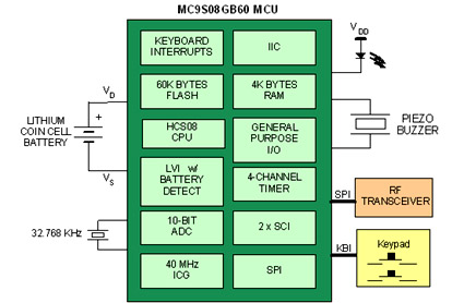
Battery-powered devices, such as electric toothbrushes, shavers, cell phones, PDAs, MP3 players, and remote controls, are integral to daily life. Consequently, power management has become a critical consideration for embedded designers. Microcontrollers (MCUs) provide various methods for managing power...
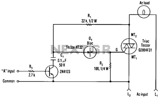
The single transistor connected between the capacitor and the common side of the AC line allows a logic-level signal to control this TRIAC power circuit. Resistor R2 prevents false triggering of the TRIAC by the trickle current through the...
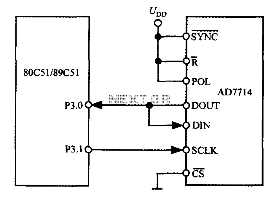
The 3-wire interface to the AD7714 can be utilized with various microcontrollers, including microcontrollers and microprocessors. This 3-wire serial interface is particularly suitable for isolation systems, allowing the use of optical couplers. The interface circuit between the AD7714 and...
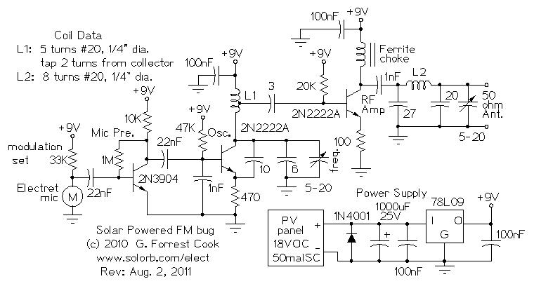
Numerous miniature FM transmitter bug circuits are available online; however, this particular design is distinctive as it operates entirely on solar power, eliminating the need for a battery. The transmitter will function as long as sunlight is incident on...
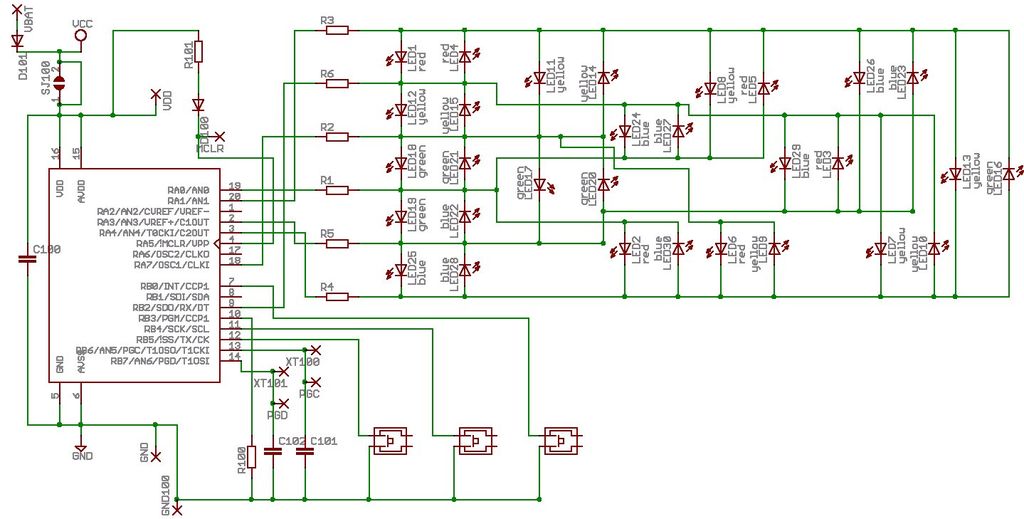
Microdot - wrist watch LED pattern timepiece. This project is a circuit board designed for creating a wristwatch-sized version. The Microdot wristwatch project involves the design and implementation of a compact circuit board that integrates LED technology to display time...
Pulse width modulation (PWM) is a technique to control analog circuits with a digital output. PWM is used in many applications, especially to control light intensity and speed on motors. A PWM circuit makes a square wave with a...