
Active crossover circuit
The described 3-way crossover circuit is designed to facilitate triamping in high-fidelity audio systems, utilizing a conventional 12 dB/octave slope characteristic of second-order Butterworth filters. The circuit is structured to improve upon traditional passive crossovers by offering enhanced performance, making it suitable for beginners and those interested in exploring multi-amping configurations without engaging in overly complex designs.
The gain settings for the filters are established using resistors Ra and Rf, achieving a gain of approximately 1.582. This value is slightly below the optimal gain of 1.586, derived from the equation k = 3 - Ao, where k is the inverse of the Q-factor for the filter design. The Q-factor for a second-order Butterworth filter is calculated to be 0.707, which provides a balance between flat pass-band gain and sharp roll-off at the cutoff frequency.
The circuit incorporates an inverting amplifier preceding the mid-range filter to address two critical issues: maintaining the gain level consistent with the low-mid and mid-high filters, and correcting phase shifts introduced by the filters. At the crossover frequency of 300 Hz, the low-mid and mid-range outputs experience a 180° phase difference, which could lead to cancellation of the signals. The inverting amplifier, with a gain of -0.63, compensates for this phase shift, ensuring coherent signal output.
The design also allows for the potential use of a fourth-order filter, which would mitigate the phase-reversal issue at the crossover points, although it would necessitate additional inverting stages to manage the mid-range gain. The capacitor (Cin) valued at 0.1µF, in conjunction with resistor R5, sets the lower 3 dB frequency at approximately 15 Hz, contributing to the overall frequency response of the crossover.
The circuit's performance is further influenced by the selection of op-amps, with the TL074 quad op-amps recommended due to their high slew rate. Resistors employed in the circuit are specified as 1/4 W, 1% metal film types to ensure precision and reliability. The inclusion of 100 Ohm resistors at the filter outputs is essential for interfacing with power stages, especially when utilizing connectors or shielded leads.
It is important to note that increasing the Q-factor beyond 0.707 results in pronounced peaking at the cutoff frequency, while decreasing it leads to a more gradual filter response. The design stipulates that the gain for each filter must remain below 3 to prevent oscillation, emphasizing the need for careful consideration of component values and configurations for optimal performance.A simple 3-way crossover, intended for triamping Hi-Fi systems. This is a conventional 12dB / Octave unit, and cannot be expected to have the same performance as a Linkwitz-Riley aligned filter network. It will still be a vast improvement over nearly any passive crossover, and is ideal for beginners or those who want to experiment further with multi-amping, but without the complexity of a major project.
The retuning (to (sub)-Bessel / Linkwitz-Riley alignment) is recommended, as the performance will be more in line with modern standards - see information below. The crossover is based on the 2nd order Butterworth filters. The resistors Ra and Rf set the gain of each filter to 1.582, which is slightly less than the required value of 1.586. This value of gain (Ao) follows from the formula ... k = 3 - Ao where k = 1 / (Q-factor of the filter). For a 2nd order filter, the value of k can be obtained from the butterworth circle for n = 2. It turns out that k = 1 / cos(x), where x = ? / (2 * n) which is ? / 4 in this case. Thus for a butterworth response, the Q-factor turns out to be 0.707. Please see references (1) for more details. Note that the mid-range filter is preceded by an inverting amplifier. This is needed for 2 reasons - Firstly, the gain of the mid-range is (1.582 * 1.582) which must be brought back to the level of the low-mid & mid-high ranges (1.582).
Secondly (and more importantly), the 2nd order butterworth filter has an inherent property of shifting the phase of any signal passing through it depending on the signal's frequency so that at cut-off the signal is 90° out of phase with the input (direction of shift depends on whether the filter is high-pass or low-pass). Thus at 300 Hz the low-mid range filter has shifted the signal by 90° and the mid range has also done the same (but in an opposite direction).
Hence, at 300 Hz, the signals appearing at the low-mid range & mid range outputs are going to be 180° out of phase with each other & will cancel out (electrically or acoustically). The same happens to the mid range & mid-high range filters at 3000 Hz. The inverter, with a gain of -0.63 serves to solve both the problems. Using a 4th order filter (assuming it to be a cascade of two 2nd order butterworth types) in place of the ones shown will not have the phase-reversal at x'over problem, but you will still need to bring down the mid range filter's gain (this equates to 2 inverters).
The 0.1µF capacitor (Cin) is used with R5 to obtain a lower 3db frequency of about 15 Hz. With the arrangement shown, the overall magnitude response exhibits peaks at the x'over frequencies when the 3 outputs are combined, either electrically or acoustically. This ordinarily does not pose a problem, since the speaker deficiencies themselves will tend to hide (rather veil) the peaks, but with really good speaker systems, the peaking could become evident.
The op-amps used should preferably have a high slew rate and all resistors must be of 1/4 W, 1% metal film type. For the x'over that I have made, the op-amps used are TL074 quad devices. Any other op-amps of your choice can be substituted in place of these. The 100 Ohm resistors at the filter outputs are required if the x'over is going to be connected to the power stages via connectors or any length of shielded lead.
Increasing Q beyond this results in peaking at the cut-off frequency for each individual filter. Likewise, reducing Q makes the filter response more and more gradual. Thus a value of 0.707 for the Q-factor gives the flattest pass-band gain & sharpest roll-off at cut-off frequency. Note that the gain of each individual filter must be less than 3, otherwise the circuit will oscillate.
To get an even sharper roll-off the order of the filters must be increased (keeping Q = 0.707). 🔗 External reference
Related Circuits
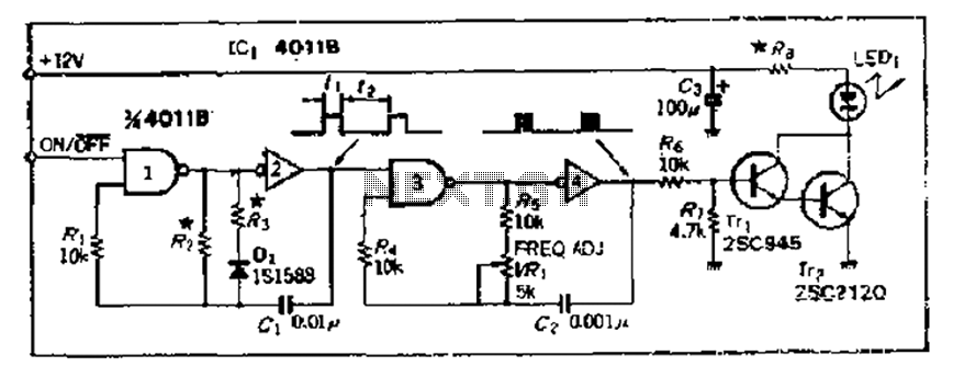
The 4000 Series 4011B is a NAND gate used in conjunction with a 4AI NAND gate circuit group to create two loops of an unstable multivibrator. The first NAND gate and the second NAND gate operate at approximately 1...
This document details the AT Keyboard Interface and AT Keyboard Protocols. It includes an example of a Keyboard to ASCII decoder utilizing a 68HC705J1A microcontroller. The AT Keyboard Interface is a standard communication protocol used primarily in personal computers to...
An infrared reflective burglar alarm utilizes infrared detection through reflective components, with a maximum detection range of up to 12 meters to trigger an alarm. When an intrusion is detected, a realistic barking sound is emitted to alert the...
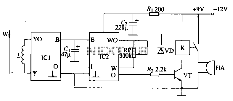
Very often when enjoying music or watching TV at high audio level, we may not be able to hear a telephone ring and thus miss an important incoming phone call. To overcome this situation, the circuit presented here can...
Using a K-12 tube amplifier with a NAD C542 CD player eliminates the necessity for a buffer or line-level preamplifier. The K-12 amplifier is characterized by its polite and sweet sound, embodying the warmth typical of its "hot bottle"...
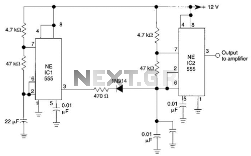
IC1 generates a pulse that modulates the 1000-Hz tone generated by IC2. This circuit can be used to generate warning or alert signals. The circuit described consists of two integrated circuits (ICs), where IC1 is responsible for generating a pulse...