
1000Hz Pulsed Tone Alarm Circuit

The circuit described consists of two integrated circuits (ICs), where IC1 is responsible for generating a pulse signal that modulates the output tone produced by IC2. The modulation process alters the amplitude or frequency of the 1000-Hz tone, resulting in a variable signal that can be used for various applications, particularly in alerting systems.
IC1 may be configured as a timer or oscillator, depending on the desired pulse characteristics, such as frequency and duty cycle. This configuration allows for flexibility in the modulation process, enabling the generation of different alert patterns. IC2, on the other hand, functions as an audio frequency generator, specifically tuned to produce a stable 1000-Hz tone.
The output from IC2 serves as a continuous tone, which is then modulated by the pulse generated by IC1. The modulation can create a range of warning signals, such as beeps or sirens, depending on the pulse width and frequency settings of IC1. This makes the circuit suitable for applications in alarms, timers, and other signaling devices where an audible alert is required.
To enhance the effectiveness of the circuit, additional components such as resistors, capacitors, and possibly a speaker or buzzer may be included in the schematic. These components can help in shaping the output signal and ensuring that the alert is both audible and distinct. Proper power supply considerations must also be taken into account to ensure reliable operation of both ICs.
Overall, this circuit design provides a simple yet effective solution for generating modulated alert signals, making it a valuable addition to various electronic systems that require sound-based notifications. IC1 generates a pulse that modulates the 1000-Hz tone generated by IC2. This circuit can be used to generate warning or alert signals.
Related Circuits
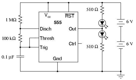
The 555 integrated circuit is a versatile timer that can be used for various applications. This experiment focuses on its operation as an astable multivibrator or oscillator. When connected to a capacitor and two resistors, it generates a square-wave...
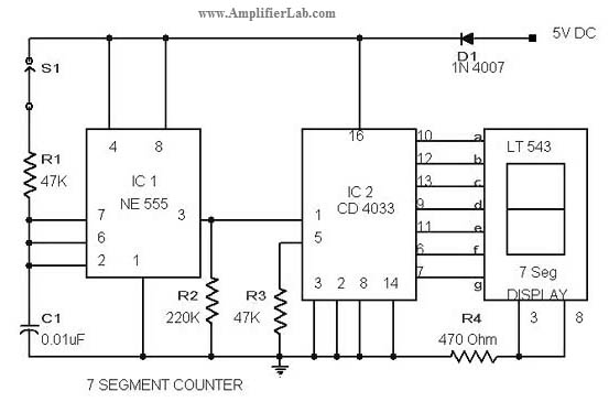
The circuit diagram of a 7-segment counter circuit has been published here. This circuit consists of the counter IC CD4033 as its central component. The 7-segment counter circuit utilizing the CD4033 integrated circuit (IC) is designed to display decimal digits...
The High Power Amplifier offers significant advantages, featuring a 5000W ultra-light, high-power audio amplifier without a switching-mode power supply. This device functions as a 2 x 2, 500W RMS stereo amplifier, designed to be super-lightweight and operates after the...

Building a signal generator is an essential project for any analog DIY enthusiast. While already possessing a bench signal generator, the intention was to create a compact, battery-powered device for quickly testing new effect designs. An enclosure from a...

This small device can be aimed at a television to jam the remote control signal. The circuit design is straightforward. A 555 timer is configured as an astable multivibrator operating at a frequency of approximately 38 kHz, which is...
In this circuit, the 555 Timer IC is configured as an astable multivibrator, and a 12-volt relay is operated through pin 3 of the IC. The IC generates continuous pulses at pin 3, which activate and deactivate the relay,...