
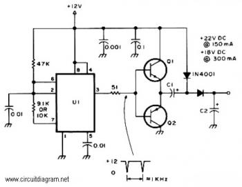
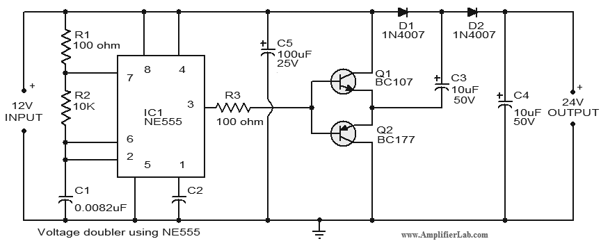
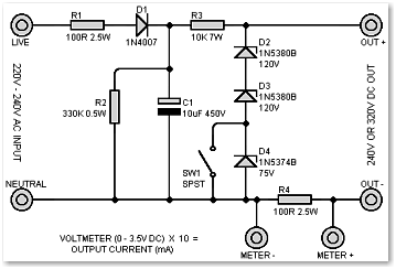
Active Voltage Doubler
The Active Tone Control circuit, or ACTOR, is engineered to modify audio signals in a way that enhances listener experience by allowing users to fine-tune bass and treble levels actively. The Baxandall tone control circuit is a popular configuration for achieving this, as it provides smooth and musical adjustments to the audio signal without introducing significant distortion.
The active antenna circuit is designed to improve reception quality for various radio bands. By utilizing a compact form factor, this circuit effectively mimics a longer wire antenna, which is particularly beneficial for portable or space-constrained applications. The active antenna amplifies weak signals, making it an ideal choice for inexpensive receivers that lack built-in tuners.
The NE555 timer-based electronic siren circuit is straightforward yet effective. The astable multivibrator configuration generates a square wave signal at a frequency of approximately 300 Hz, which can be adjusted by varying the voltage at pin 5. This feature allows for customization of the siren tone to suit specific applications, such as alarms or alerts.
In the fire alarm circuit, the thermistor serves as a critical component for temperature detection. As the temperature rises, the thermistor's resistance decreases, allowing current to flow and activating the connected transistor, which can trigger an alarm or alert system. This simple yet effective design is suitable for various safety applications.
The positive voltage regulator circuit with the PNP boost transistor ensures a stable output voltage, vital for powering sensitive electronic components. The use of the IC8211 for voltage regulation simplifies the design while ensuring reliable performance. The inclusion of capacitors for stability and transient suppression enhances the overall robustness of the circuit.
Finally, the adjustable power supply circuit offers flexibility in powering a variety of devices. By allowing users to set the output voltage within a specified range, this circuit can cater to different voltage requirements, making it a versatile addition to any electronics project. The specified components provide a clear guide for constructing the circuit effectively.The following diagram is the schematic diagram of Active Tone Control circuit, or we often call thic circuit as "ACTOR" Active Tone Control or ACTOR is a electronic audio circuit that serves to increase the Loudness (Bass and Treble audio signal) is active because it uses the Baxandall system. This circuit does not use a. This is an active antenn a for FM radio receiver, AM radio receiver and SW (shortwave) radio receiver. On the shortwave band this active antenna is comparable to a 20 to 30 foot wire antenna. This circuit is designed to be used on receivers that use untuned wire antennas, such as inexpensive units and car radios. . Here the circuit diagram of electronic siren based NE555. This circuit produces a sound like factory siren. It applies a 555 timer IC which is utilized as an astable multivibrator of a center frequency of about 300Hz.
The frequency is controlled by the pin 5 of the IC. When the power supply is switched ON, . The following circuit is a simple fire alarm circuit based NE555 timer and use thermistor as a temperature detector. This sensor will activate the transistor when the temperature is in high value. The thermistor will have a low resistance at high temperature, while at low temperature, the transistor resistance is high.
This characteristic of thermitor. Positive voltage regulator circuit with PNP Boost transistor The IC8211 presents the voltage reference and regulator amplifier, while Q1 will be the series pass transistor. R1 defines the output current of the IC8211, while C1 and C2 present loop stability and as well act to suppress feedthrough of input transients to the output supply.
R2. This is an adjustable power supply which have adjustabled output voltage from 6-12 DC volt. Component Parts List: T1 = 115[220]/8 VAC transformer. Center Tap not needed. Q1 = 2N1613, NTE128, or substitute. (TO-39 case) On coolrib! BR1 = 40V, 4A. (Check max current of your mini-drill and add 2A) R1 = 470 ohm, 5%. 🔗 External reference
Related Circuits
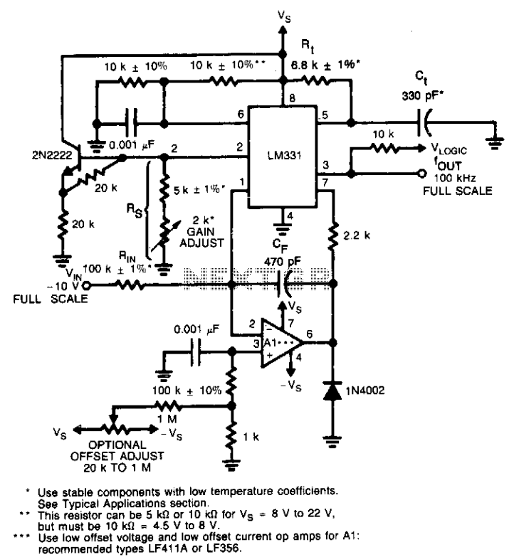
This circuit utilizes a conventional operational amplifier in conjunction with a feedback capacitor (CF) to perform integration. When the output of the integrator exceeds the nominal threshold level at pin 6 of the LM131, it triggers the timing cycle....
Project Manager Jim Heck, G3WGM, has provided an exclusive audio interview to Bob McCreadie, G0FGX, from TX Factor, detailing the tests and potential issues involved. Membership in AMSAT-UK is available to anyone interested in amateur radio satellites or space...
A functional circuit utilizing an operational amplifier (op-amp); however, the instructor indicated that op-amps can be challenging to work with and provided transistors as an alternative. Operational amplifiers (op-amps) are versatile components commonly used in various electronic circuits for...
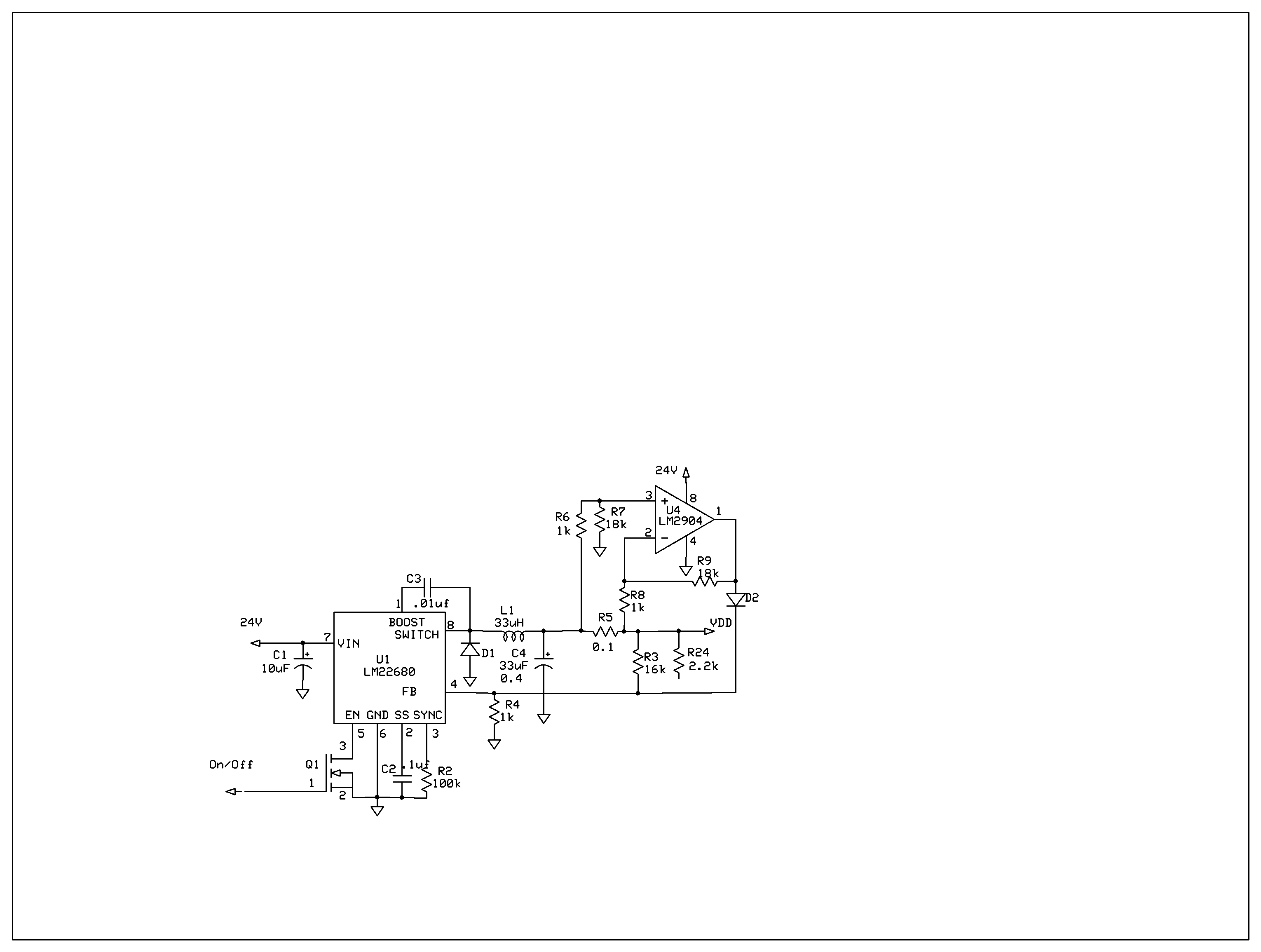
The product requires a voltage-controlled, current-limited power supply. Various switcher chips have been used with an op-amp to provide feedback for a current sense voltage to the feedback pin. Currently, an LM22680 is in use, but it has shown...
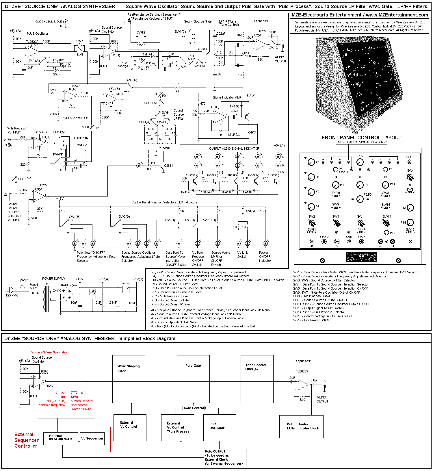
Low-pass and high-pass audio output signal filters are included. An additional sound source low-pass filter and an experimental original design pulse-gate signal filter ("processor") are available, both featuring independent or linked voltage control input options. The synthesizer can function...
High voltage electrolytic capacitors in valve equipment can deteriorate if the equipment is unused for an extended period. This deterioration manifests as reduced capacitance and significantly increased leakage current. In some instances, the capacitor may become nearly short-circuited. Using...
Warning: include(partials/cookie-banner.php): Failed to open stream: Permission denied in /var/www/html/nextgr/view-circuit.php on line 713
Warning: include(): Failed opening 'partials/cookie-banner.php' for inclusion (include_path='.:/usr/share/php') in /var/www/html/nextgr/view-circuit.php on line 713