
Adjustable Current Limit For Dual Power Supply
The current-limiting circuit described functions effectively to protect the dual voltage regulator from overload conditions while providing adjustable current limits for various applications. The configuration of the LM317 and LM337 in conjunction with resistors allows for smooth adjustments to the output current, accommodating a range of operational requirements. The choice of resistor values and the method of dividing them into two components ensures practicality in achieving the desired current limits without the need for rare components. Additionally, the careful consideration of input voltage requirements and capacitor sizes enhances the reliability and performance of the power supply circuit, making it suitable for diverse electronic projects. The overall design emphasizes efficiency and flexibility, providing a robust solution for applications requiring precise voltage regulation and current limiting.This current-limiting circuit, shown in this example as part of a small bench power supply, could in principle be used in conjunction with any dual-rail current source. The part of the circuit to the left of the diagram limits the current at the input to the dual voltage regulator (IC4 to IC7) so that it is safely protected against overload.
The c ircuit shown produces outputs at ±15 V and ±5V. The voltage regulators at the outputs (7815/7805 and 7915/7905) need no further comment; but the current-limiting circuit itself, built around an LM317 and an LM337, is not quite so self-explanatory. The upper LM317 (IC1) manages the current limiting function for the upper branch of the circuit. The clever part is the combination of the two resistors R1 and R3 between the output and the adjust input of the regulator.
In the basic LM317 configuration in current-limiting mode (i. e. , as a constant current source), just one resistor is used here, across which the regulator maintains a constant voltage of 1. 25 V. The current is thus limited to a value of 1. 25 V/R. To obtain a maximum current of 1 A, for example, the formula tells us that the necessary resistor value is 1.
25R. Unfortunately it is not practical to try to build an adjustable dual-rail current-limited supply in this way, as stereo potentiometers with a value of 1. 2R are extremely difficult, if not impossible, to obtain. We can solve the problem using the technique of dividing the resistor into two resistors. Only the resistor at the output of the LM317 (R1) serves for current sensing. The second resistor (R3) causes an additional voltage drop depending on an additional (and adjustable) current.
When the sum of the two voltages reaches 1. 25 V current limiting cuts in. This makes it possible to adjust the current limit smoothly using the current in the second resistor (R3). This can be done simultaneously in the positive and negative branches of the circuit, as the diagram shows.
It would of course be wasteful to arrange for the current flowing in the second resistor to be of the same order of magnitude as the current in the main resistor. We therefore make the value of the second resistor considerably greater than that of the main one. If the main resistor (R1) has a value of 1. 2R (giving a maximum current of 1 A), and the second resistor (R3) a value of 120R, the necessary voltage drop is achieved using an extra current of 10 ent limit will be 1 A.
For the negative branch of the circuit the LM337, along with resistors R2 (1. 2r) and R5 (120R), performs the same functions. A further LM317 (IC3) is used to set the overall current limit point by controlling the additional current. The resistance used with this voltage regulator, wired as a current sink (R4 in series with P1) determines the additional current and therefore also the output current in both the negative and positive branches of the circuit.
Since we also want the total resistance of R4 and P1 to be 120R, we use a value of 22R for R4 and 100R for P1 to give a wide adjustment range for the output current from a few milliamps to 1A. The minimum input voltage for the circuit depends on the desired output voltage and maximum output current.
The input to the 7815 should be at least 18 V. We should allow approximately a further 1. 2 V + 2. 2 V for the voltage drops across IC1 and R1. If we allow a total of 4V for the current limiting circuit in each branch, this means that the circuit as a whole should be supplied with at least ±22 V to produce well-regulated outputs at ±15 V and ±5V. If the symmetrical input voltage is to be provided using a single transformer winding, two diodes and two smoothing capacitors, it important to ensure that the capacitor values are sufficiently large, as there will be considerably more ripple than there would be with full-wave rectification.
Depending on the application, capacitors C6 to C9 at the outputs of the fixed voltage regulators can be electrolytics with a value of 4. 7 µF or 10 µF. To improve stability, electrolytic capacitors can also be connected in parallel with C1, C2, C4 and C5.
🔗 External reference
Related Circuits
A 12V power supply is an essential and useful resource for laboratories, as it is employed by a wide range of electronic circuits and devices. A 12V power supply circuit can be constructed based on specific ampere requirements. A...
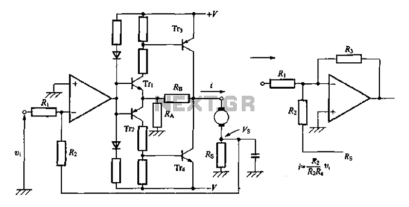
A discrete transistor current control circuit diagram. The discrete transistor current control circuit is designed to regulate the flow of current through a load by utilizing a transistor as the primary control element. This circuit typically consists of a few...
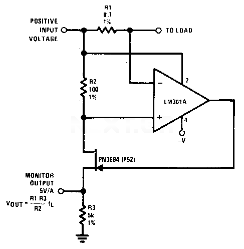
The resistor (Rl) senses the current flow of a power supply. The JFET is utilized as a buffer since Id equals Is; thus, the output monitor voltage accurately represents the current flow of the power supply. In this circuit, Rl...
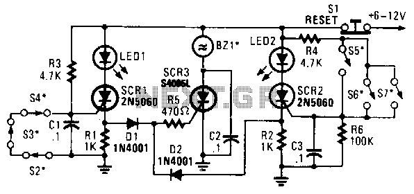
In this circuit, a low-powered silicon-controlled rectifier (SCR) is utilized to trigger a higher-powered SCR. When a switch is opened (S2, S3, S4) or closed (S5, S6, S7), either SCR1 or SCR2 is activated. This action subsequently triggers SCR3...
Utilizing a low-cost high-side precision current monitor to prevent excessive load currents from damaging power supplies. The implementation of a high-side precision current monitor is an effective strategy for protecting power supplies from excessive load currents. This type of current...
40V regulated power supply based on TIP42A and LM317. Refer to the specified page for an explanation of the related circuit diagram. The 40V regulated power supply utilizes a TIP42A transistor and an LM317 voltage regulator to provide a stable...
Warning: include(partials/cookie-banner.php): Failed to open stream: Permission denied in /var/www/html/nextgr/view-circuit.php on line 713
Warning: include(): Failed opening 'partials/cookie-banner.php' for inclusion (include_path='.:/usr/share/php') in /var/www/html/nextgr/view-circuit.php on line 713