
High-Power Alarm Driver Circuit
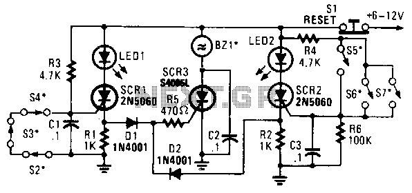
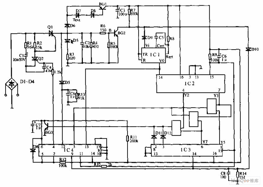
The presented circuit employs a low-powered SCR to control the activation of a higher-powered SCR, which is a common configuration in electronic control systems where isolation and amplification of control signals are required. The operation begins with the status change of switches S2, S3, S4, S5, S6, or S7. Each switch corresponds to specific operational conditions that dictate whether SCR1 or SCR2 will be triggered.
Upon the closure or opening of these switches, a corresponding SCR is activated, allowing current to flow through the circuit. The activation of either SCR1 or SCR2 leads to the conduction of current through diodes D1 and D2. These diodes are essential for protecting the circuit by ensuring that current flows in the correct direction, thus preventing any potential damage due to reverse polarity.
Resistor R5 plays a crucial role in this circuit by limiting the current flowing to SCR3. This is important for ensuring that SCR3 operates within its specified parameters, avoiding any risk of damage due to excessive current. Once SCR3 is triggered, it activates BZ1, which is a high-powered alarm designed to alert users of a specific condition. The interrupting type alarm indicates that it will produce sound or signal interruptions upon activation, providing immediate feedback regarding the circuit's state.
This configuration is particularly useful in applications such as safety systems, alarm systems, or any scenario where a low-power signal needs to control a more significant load. The combination of SCRs and diodes in this circuit effectively demonstrates the principles of controlled rectification and signal amplification, ensuring reliable operation in response to user inputs. In this circuit, a low-powered SCR is used to trigger a liigher powered SCR. When a switch is opening (S2, S3, S4) or closing (S5, S6, S7), either SCR1 or SCR2 triggers. This triggers SCR3 via Dl, D2, and R5. BZ1 is a high-powered alarm of the on interrupting type. 🔗 External reference
Related Circuits
These small electronic lamps are quite practical and have a long lifespan. Approximately 40 years after Nick Holonyak invented the first LED, they have become nearly essential. Any dedicated electronics enthusiast typically keeps a few in their collection. Prior...
When the water level is below the steel rods, there is no contact between the metal can and the rods, which are supported by a small insulated wooden board. The small circuit built around IC1 does not draw any...
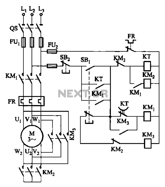
The circuit depicted in Figure 3-41 illustrates a Y-transfer process. When contact KMi is turned off, the motor undergoes a transition in the event of a power failure. Additionally, the main contact KM3 is disconnected when KM2 is activated,...
This amplifier circuit is designed to enhance TV signals in the UHF range. It employs a low-noise transistor, providing an amplification of 10 to 15 dB within the frequency spectrum of 400 MHz to 850 MHz. It is crucial...
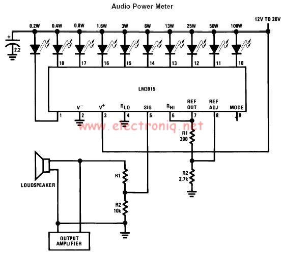
The LM3915 monolithic integrated circuit can be used to design a simple audio power level meter that senses analog voltage levels and drives ten LEDs, LCDs, or vacuum fluorescent displays, providing a logarithmic 3 dB/step analog display. One pin...
The pulse telephone 160 168 controller circuit is depicted above. This controller can be installed either on the telephone or on the switchboard of the trunk line. It effectively prevents unauthorized dialing of numbers 160 and 168. Diodes D1...
Warning: include(partials/cookie-banner.php): Failed to open stream: Permission denied in /var/www/html/nextgr/view-circuit.php on line 713
Warning: include(): Failed opening 'partials/cookie-banner.php' for inclusion (include_path='.:/usr/share/php') in /var/www/html/nextgr/view-circuit.php on line 713