
Adjustable filter provides lowpass response
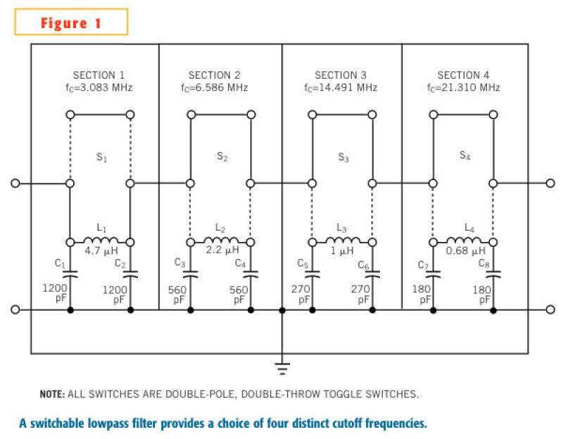
The adjustable lowpass filter described is a versatile circuit designed to attenuate frequencies above a certain cutoff while allowing lower frequencies to pass through. Each filter section is constructed using standard components, specifically Coilcraft 90 series axial-lead chokes for inductance and polypropylene capacitors. The design avoids the complexity of additional components in series or parallel, simplifying assembly and maintenance.
The filter is housed in a Bud CU-123 die-cast aluminum enclosure, which provides both durability and shielding from external electromagnetic interference. The dimensions of 3.625 inches in length, 1.5 inches in width, and 1.0625 inches in height contribute to a compact design suitable for various applications. Input and output connections are facilitated through BNC connectors, ensuring reliable connectivity.
Each of the four filter sections is equipped with a miniature toggle switch located on the enclosure's exterior, allowing for easy adjustment of the filter settings. The internal ground returns are implemented using solder lugs, which provide a solid electrical connection and minimize the risk of ground loops.
The filter sections are engineered to maintain a characteristic impedance of 50 Ohms, which is critical for minimizing signal reflections and ensuring maximum power transfer. The nominal 3-dB cutoff frequencies of 3.083 MHz, 6.586 MHz, 14.491 MHz, and 21.310 MHz are designed to cater to a range of applications, from audio processing to RF signal filtering.
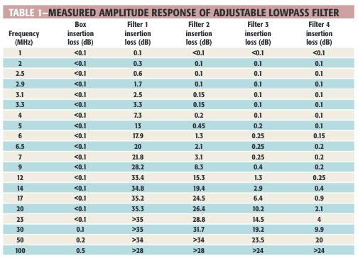
Performance testing indicates that while the filter operates effectively within its specified frequencies, there is a degradation in transmission performance as the frequency approaches 100 MHz, particularly when all filter sections are switched off. This performance drop can be attributed to the parasitic elements introduced by the enclosure and the bus wire interconnections, which contribute to stray inductance estimated at approximately 55 nH.
In summary, this adjustable lowpass filter offers a practical solution for frequency management in electronic circuits, combining ease of use with effective filtering capabilities. The design emphasizes the importance of component selection and layout in achieving desired electrical performance while maintaining a user-friendly interface.In an adjustable lowpass filter, each filter section uses commonly available components (Figure 1). This example uses filter-section cutoff frequencies for standard inductors and capacitors without the need for any extra components in series or parallel. Fixed inductors are Coilcraft 90 series axial-lead chokes with ±10% tolerance. Fixed capacitors are polyropylene units, available from any distributor, with ±2% tolerance for the 1200-pF devices and ±5% tolerance for the other values.
The adjustable lowpass filter is in a 3.625-in.-long×1.5-in.-wide×1.0625-in.-high Bud CU-123 die-cast aluminum box with input and output BNCs. Miniature toggle switches for the individual filter sections are accessible at the enclosure's exterior.
Internal ground returns use solder lugs. The four filter sections have 50Ohm characteristic impedance and nominal 3-dB cutoff, from left to right in Figure 1, of 3.083, 6.586, 14.491, and 21.310 MHz. Table 1 shows the measured amplitude response for the box alone and for the four individual filter sections.
The low-cost, adjustable lowpass filter delivers reasonable performance. As the frequency approaches 100 MHz, the transmission performance of the enclosure deteriorates with all filter sections switched to the off position. The interconnections between switched sections use available bus wire without any precautions to minimize parasitic circuit elements.
Stray series inductance, estimated at approximately 55 nH, arises from the 3.5-in. physical length of the enclosure, plus 2 in. for the four switches.
Related Circuits
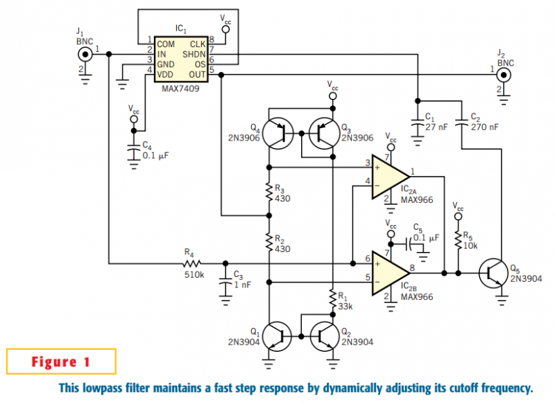
The circuit in Figure 1 accommodates lower cutoff frequencies without sacrificing the step-response time. A window comparator monitors the delta (difference) between the filter's input and output. When the delta exceeds ±50 mV, the filter increases its slew rate...
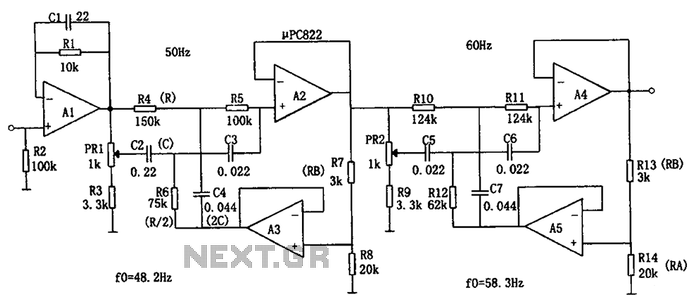
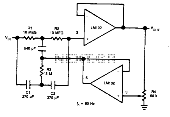
The circuit depicted in the figure is a frequency power supply noise filter circuit, specifically a double-T filter. It is designed to amplify weak signals, such as those from sensors, while filtering out mixed 50Hz (or 60Hz) power supply...
One application of this handy circuit is a graphic equalizer, created by feeding a signal to a number of parallel band-pass filters each tuned to a different frequency; typically octaves apart. Then, you can adjust the strength in each...
In applications where the rejected signal may slightly deviate from the null point in a notch network, it is beneficial to decrease the Q factor of the network. This adjustment ensures consistent rejection across a broader range of input...
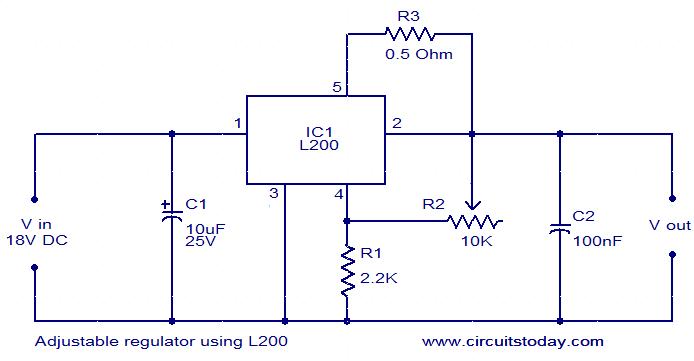
The circuit diagram depicts an adjustable voltage regulator utilizing the IC L200. The L200 is a monolithic integrated adjustable voltage regulator IC that incorporates features such as current limiting, thermal shutdown, power limiting, and input over-voltage protection. This regulator...
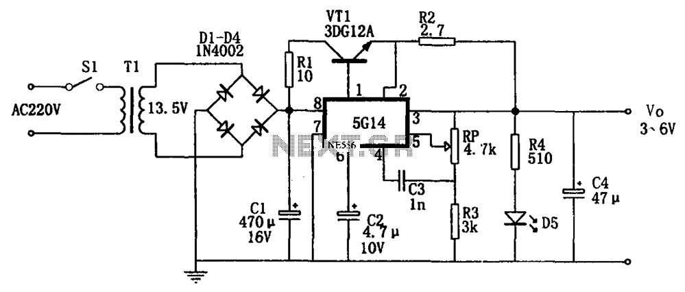
As shown in the figures, this is a practical adjustable power supply. It utilizes an integrated voltage regulator (5G14) in conjunction with a 3DG12A transistor for current spreading, providing an output voltage range of 3 to 6V. The rated...