
Lowpass filter has improved step response
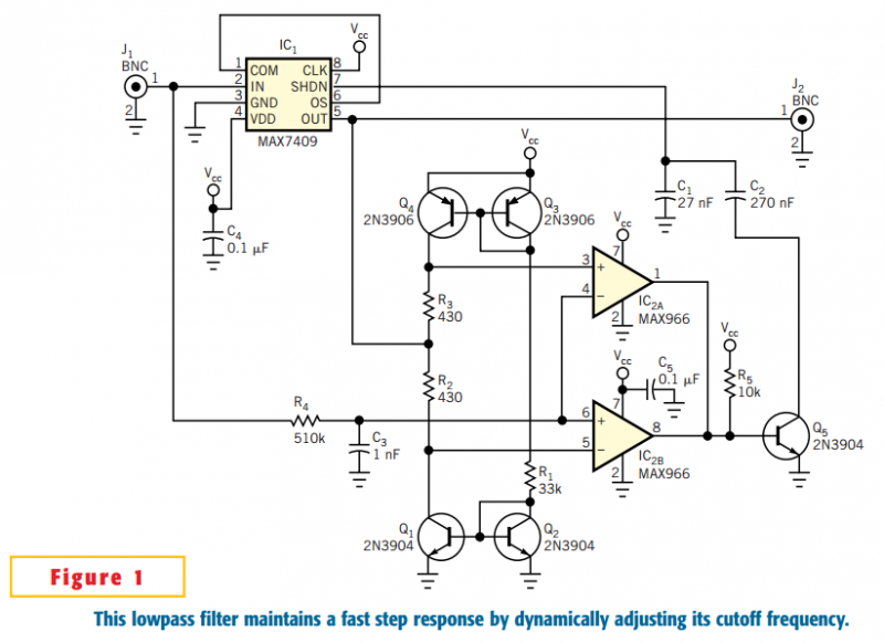
The described circuit utilizes a switched-capacitor filter (IC1) to achieve low cutoff frequencies while maintaining rapid response times. The architecture employs a window comparator that continuously monitors the voltage difference between the input and output signals. The comparator is designed to trigger when this delta voltage exceeds ±50 mV, effectively enabling the filter to adjust its cutoff frequency dynamically.
Capacitors C1 and C2 are critical components, as they establish a baseline cutoff frequency of 0.1 Hz for the filter. The dynamic window comparator is constructed using transistor pairs Q1-Q2 and Q3-Q4, which form a complementary current mirror. This configuration allows precise control over the output current flowing through resistors R2 and R3, which are integral in creating the specified ±50 mV delta. The output voltage is connected to the center tap of the resistors, ensuring that the window comparator thresholds are symmetrically set at VOUT+50 mV and VOUT–50 mV.
To further enhance performance, resistors R4 and capacitor C3 are implemented to provide lowpass filtering of the input signal, achieving a cutoff frequency of 312 Hz. This additional filtering is essential for reducing the circuit's sensitivity to transient glitches, thus stabilizing the input to the window comparator. If the filtered input signal exceeds the defined voltage window, comparator IC2A or IC2B will output a low signal, which subsequently drives transistor Q5 into cutoff mode. This action results in a high-impedance state at Q5's collector, effectively disconnecting capacitor C2 from ground and allowing the filter's cutoff frequency to increase by a factor of ten.
The circuit is capable of reverting to its original cutoff frequency once the output signal returns within the ±50 mV range of the input. The oscilloscope measurements illustrate the performance of the circuit, highlighting the significant improvement in response time with the optimization circuitry engaged compared to the unmodified filter response. The design allows for flexibility in frequency scaling by adjusting the values of capacitors C1 and C2, as well as modifying resistors R2 and R3 to achieve different window voltage levels, with the delta being proportional to the resistance multiplied by 115 µA. It is essential that the window comparator used in this circuit is of the open-drain type to ensure proper functionality.The circuit in Figure 1 accommodates lower cutoff frequencies without sacrificing the step-response time. A window comparator monitors the delta (difference) between the filter's input and output. When the delta exceeds ±50 mV, the filter increases its slew rate by increasing the cutoff frequency by an order of magnitude.
The switched-capacitor filter, IC1, normally operates as a self-clocked device. Capacitors C1 and C2 set the cutoff frequency at 0.1 Hz, and other circuitry forms a dynamic window comparator. Transistor pairs Q1-Q2 and Q3-Q4 form a complementary current mirror whose output flows through R2 and R3, creating a delta of ±50 mV.
Connecting the output voltage to the center tap of the two resistors centers the delta on the output voltage. You therefore set the window comparator's upper threshold at VOUT+50 mV and the lower threshold at VOUT–50 mV.
R4 and C3 provide lowpass-filtering to the original input signal, producing a 312-Hz cutoff frequency that reduces sensitivity to momentary glitches. The filtered input drives the window comparator's input. If that input is outside the ±50-mV window, comparator IC2A or IC2B asserts its output low. The low output drives Q5 into cutoff, causing its collector to assume a high impedance. Because Q5's collector no longer grounds capacitor C2, the filter's cutoff frequency increases by a factor of 10.
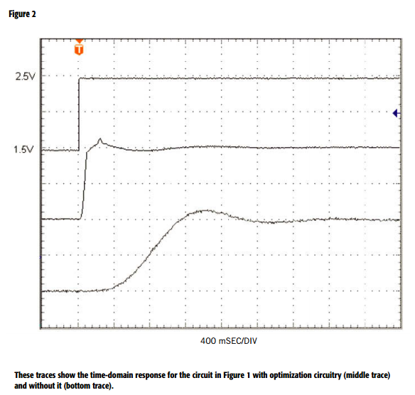
When the system's output changes to within 50 mV of the input, the cutoff frequency throttles back to its quiescent state. Figure 2's oscilloscope photo shows the effect. The top trace is a step from 1.5 to 2.5V, the middle trace is the output with optimization circuitry enabled, and the bottom trace shows the filter's unmodified response.
The optimized response includes a slight perturbation during the cutoff-frequency transition, but is five times faster than that of the unmodified circuit. The circuit in Figure 1 is configured for low cutoff frequencies, but you can rescale it for higher frequencies by changing C1 and C2.
You can also modify R2 and R3 for different window values, for which the delta equals the resistance multiplied by 115 µA. The comparator must be an open-drain type.
Related Circuits
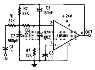
Designed to produce a 12-dB/octave roll-off above the 10-kHz cutoff frequency, this low-pass active filter will help reduce needle scratch on records. It utilizes an LM387 low-noise amplifier integrated circuit (IC). The low-pass active filter described is engineered to attenuate...
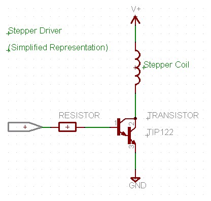
This program initializes all sixteen I/O lines of the U4x1 to function as outputs. The lower four port pins of port A (A0 - A3) correspond to "channel 1" for stepper motor activity, while the upper four port pins...
M1 is a stepper motor salvaged from an old disk drive. It features five pins: common, coil 1, coil 2, coil 3, and coil 4. The resistance measured between the common pin and each coil is approximately 75 Ohms....
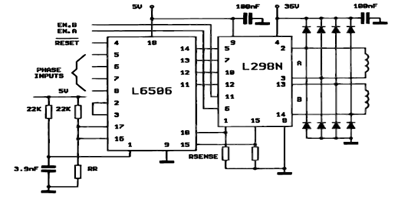
The following figure illustrates the control circuit for a two-phase bipolar stepper motor utilizing the current controller L6506. The L6506 integrated circuit generates the necessary signals to drive the inputs of the L298 bipolar stepper motor circuit driver. The circuit...
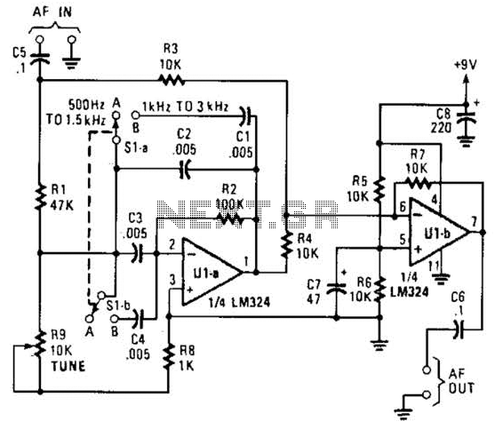
The notch filter can be integrated into nearly any receiver to attenuate a specific frequency by over 30 dB. This filter is particularly useful for diminishing heterodynes and whistles. A notch filter, also known as a band-stop filter, is designed...
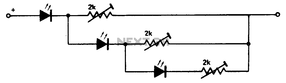
This circuit creates a compact level indicator suitable for situations where a traditional meter would be impractical or cost-prohibitive. The resistor values are contingent upon the type of LED utilized. For MV50 LEDs, resistor values of 2 kΩ are...