
All Lights Go Out When Brakes Lights Should Be On
In addressing the wiring issues of the boat trailer, it is crucial to ensure that all electrical connections are secure and that the ground circuit exhibits minimal resistance. The use of a standard 4-pole flat connector is typical for trailer lighting systems, providing a straightforward method for connecting the trailer's lighting to the tow vehicle. The wiring harness should be inspected for any signs of wear, corrosion, or damage, particularly at connection points.
To enhance the reliability of the trailer lighting system, it may be beneficial to implement a dedicated ground wire from the trailer lights directly to the vehicle's chassis, bypassing any potential high-resistance connections that may exist in the existing ground path. This can help minimize voltage drops and ensure that all lights function optimally, particularly when higher current draw components such as brake lights are activated.
Additionally, the use of LED lights for trailer applications can be advantageous due to their lower current draw compared to traditional incandescent bulbs. This can reduce the overall load on the circuit and help mitigate issues related to voltage drop across the ground path.
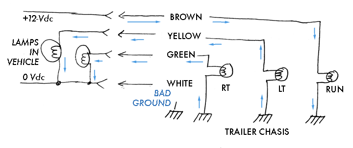
Regular maintenance and testing of the trailer's electrical system can prevent issues from arising, ensuring safe and reliable operation during towing. Utilizing a multimeter to measure voltage at various points in the circuit can help identify areas of high resistance and facilitate troubleshooting efforts.had to rewire a boat trailer due to damaged wiring and lights. I`m using a standard 4 pole flat connection to my truck. The trailer is simple - two rear lights and nbo side markers. Both rear lights are grounded to the harness to the truck. Almost everything works fine. Turn on the headlights and the trailer lights are both on. Both turn signals work. When I have my truck lights off, the brake lights work fine on the trailer. This is a very common and classic problem. There is too much resistance in the ground or return circuit. The total current of the running iamps is small enough to keep the voltage drop across the ground resistance low enough to sustain the lamp illumination. As soon as the cold filaments of the brake lights are supplied with current, it drives the voltage drop across the return portion of the circuit so high all the lamps extinguish.
The running lamps are illuminated. The resistance in the ground circuit is higher than normal. Let us figure the current for the lamp is 1-Ampere. The ground resistance is 3-ohms. This mean there is a 3-volt drop across the ground resistance. The lamps are receiving only 9-volts, however they do illuminate at this voltage, although at reduced luminance. So the trailer lamps are burning. Ww step on the brake. The brake lamps are designed to be brighter than the running lamps, so they draw more current. This means their filament resistance is lower, and when the brake lamps are off, their filament resistance is very low, practically a dead short.
When the brake switch closes, the cold brake lamp filaments act more like wire than a lamp, and they drive the voltage drop across the ground resistance much higher, let`s say to about 9-volts. The voltage drop across the cold lamps is only about 3-volts. This is not enough to illuminate the filament. This drops the other lamps to only 3-volts across them, and they go out. Once out their filaments cool, the voltage across them drops even more. This explains why you often hear of a trailer whose lights "all work until you hit the brake. " The high current of the two extra-bright brake lamps causes the voltage drop across the ground path to be too high to sustain the other lamps.
Here is a sketch of the current flow when there is no connection or a high resistance connection between the vehicle and trailer. The resistance of the other lamps when off provides a sneak circuit for the running lamps. Thank you for the very informative and time consuming explanation to enable those of us who are "challenged" when circuit trouble shooting our wiring issues.
I tip my cap to you, Mr. Hebert! 🔗 External reference
Related Circuits
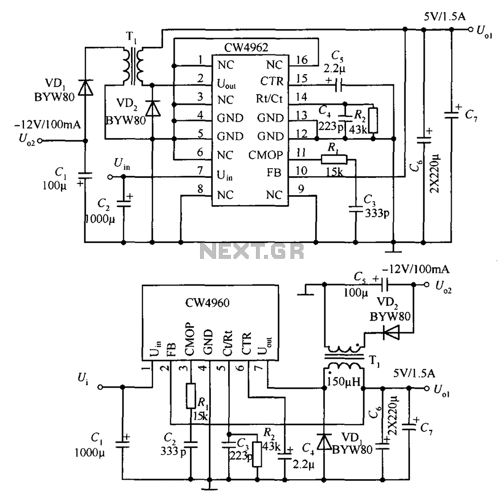
The circuit described is a stabilized power supply utilizing the CW4962 and CW4960 components, providing +5V at 1.5A and -12V at 100mA. The +5V output serves as the main power supply. The output circuit employs a transformer rather than...
A motor spins the "propeller", and a small microprocessor keeps track of time and changes the pattern on seven LEDs with exact timing to simulate a 7 by 30 array of LEDs. It is an illusion, but it works...
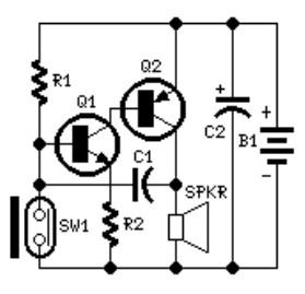
The system involves positioning a small magnet near the stalk switch SW1, which is connected to the hand or garments of the individual carrying the bag via a tiny cable. Due to the compact nature of the circuit, it...
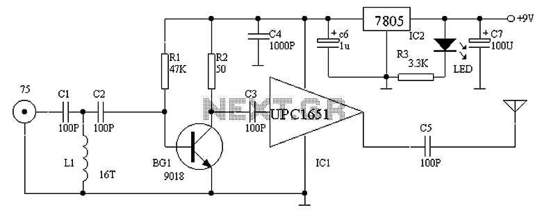
Circuit Overview Many families now own various electronic devices such as televisions, VCD players, video recorders, game consoles, cameras, and DVDs. This circuit involves an RF signal repeater designed to work with a television signal transmitter, covering a radius...
This circuit was formed to create a wireless alarm from a normal magnetic contact. By fixing the magnet to the leaf of a door, or swing of a drawer, it is easy to reveal the opening. To transmit the...
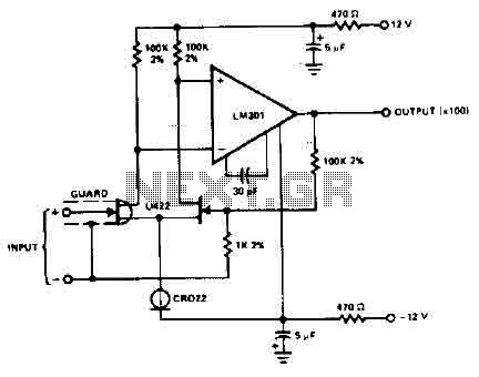
The circuit employs the LM301 operational amplifier, which has a typical input leakage current of only 2 pA at 75 °C and is utilized with an input resistance of 1 MΩ. The operating voltage requirement is ±12V. The LM301 operational...