
RF wireless allarm magnetic switch PIC16F84
More: The circuit is powered by a battery of 9 volts, connected to the terminal ends of the M1. The negative terminal of the battery goes to "mass", while the positive comes in integrating IC2, which stabilizes the voltage to 5 volts. IC2 78L05 is equivalent to the more common, but has a much lower consumption making it ideal for battery applications. IC1 is the heart of the transmitter, a microcontroller PIC16F84, the legendary American company integrated Microchip, which is programmed with the software "picrmt.bin". The foot DEFAULT (2) is connected to a jumper (JP1) by linking two three will get the codes pre-programmed into the chip, instead of connecting two three will get the code (to be included with the 'special procedure). Each of the three inputs (terminals M2, M3, and M4) has an RC network (respectively R3-C5-C6 R4, R5-C7) Interval timer that action. A simple network delay (R1, C1) provides the RESET power. The power to reach 5Volt IC1 through the legs 14 (+5 V) and 5 (ground). The capacitor C2 (weld as close as possible to the pin of IC1) clears any feeding problems. The clock is generated by OSC1, a ceramic resonator 4MHz 3-pin: to use to use a quartz (2 feet), you add two small capacitors as shown in the diagrams of the base Nutchip. The foot RF (3) connected to the positive way in the radio chip. The foot LED (17) driver LD1 is turned on at each transmission. The pulses leaving the pin OUT (18) and go to TX1, a transmitter module to the 5Volt Aurel. The transmitter module requires an antenna tuned on 433 MHz to be connected to pin ANT.
Mounting
Here are the opposite of the components on the PCB. You can also use "spacers" (using the same format and following the grid), or a breadboard spring (breadboard), because the assembly is not critical. The work is not difficult and with a minimum of patience and precision can be completed by all. Start with the lowest components (resistors), rising gradually to the highest and bulky. Better to use a socket IC1 and the module transmitter TX1 (a "strip" female will do). Be careful not to reverse the polarity of the LED, the battery, the integrated form of the capacitor C3 and TX1: if in doubt check the COMPONENTS page for details. L' antenna is connected to the piazzolina ANT, a piece of copper wire drive, 16.5 cm long, will be fine. Then if you want that extra touch, we recommend the professional model of Aurel, flexible black rubber. Once the board (and after a further check of all connections) and the first to enter the PIC and the module TX1 connect the battery taking care not to reverse the polarity. Check with a tester between pins 5 and 14 of the base of IC1 have all of the 5 volt stabilized, as well as between the pairs of legs 3:01 p.m., 3:04 p.m., 3:13 p.m. module TX1. Once the controls, remove the battery and insert the PIC (which you have previously programmed with the file "picrmt.bin") and the module TX1 (with the component side to the outside of the board). Are you ready for the final test! The remote should work now. Just connect the battery, the LED turns on for about a second, then turn on all the times that we will close the contact connected to one of the inputs.
Arrangement of the components. The grid shows the step of "spacers" (2.54 mm).
Setup Nutchip
The next step will be to "teach" the Nutchip recognize such codes. For example, this pattern of theft associated with the entry of early warning via the radio button KEY4, while KEY5 associated alarm via radio retarded. Select the "custom RF remote control" of Nutstation, click on the small buttons on the remote control that appears on the screen, and enter the following codes:
KEY4 1 = INPUT: BUTTON CODE 2721 KEY5 INPUT = IN 2: KEY CODE 2724 The third line is not used in the scheme of the anti, if you want you can still attach to the button KEY6:
KEY6 3 = INPUT: BUTTON CODE 2727 These codes are only valid if JP1 is in position 2-3. Otherwise use the learning function (you have to connect to a PC running a complete circuit of the receiver). At the end, always remember to schedule the Nutchip to give effect to the new codes. Just enter the codes in Nutstation once. The PC stores the codes until you change them again.
Parts list:
IC1: PIC16F84 programmed with the integrated file "picrmt.hex" (you download from the downloads page) IC2: Integrated stabilizer LM2936-Z5 (National). Replacing it with a common 78L05 battery life will be much shorter. R1, R3, R4, R5: 10 kohm Resistance R2: 560 ohm resistance C1, C2, C4: ceramic capacitors C3: electrolytic capacitor 47uF/16V C5, C6, C7: condenstore electrolytic 10uF/16V JP1: Jumper 3-pole, 2 positions DL1: red LED OSC: 4MHz 3 pin ceramic resonator M1, M2, M3, M4: bipolar clamp PCB, or 9 volt battery holder for battery TX1: 433 MHz transmitter module TX-type Aurel SAW433SZ Miscellaneous: 18-pin socket for IC1 socket to "strip" for TX1, 9-volt battery, antenna (see text)
Replacement parts
If you do not find all the components, you can make the sosituzioni with similar parts. Be careful though, to pin-outs, which can change from those provided in our printed circuit boards. The 'integrated stabilizer is a 5 volt regulator specifically for battery-driven appliances. Its characteristic is that they do not "eat" the battery to empty (Low Power Consumption) and power operation at low battery (low-dropout). Can be replaced by a common 78L05 (note the L) when using a power supply instead of the stack. The PIC can be either a PIC16F84 or 16F84A. The recovery is the card for digital TV. The transmitter module is not critical and can be replaced with other modules on / off 5 volts and the frequency of 433 MHz of other producers (e.g., Mipot). If you want to make a tiny transmitter then consider a model with built-in antenna (but do not expect a great extent). In fixed installations (wireless doorbell, wireless processing of infrared sensors, monitoring devices, etc.) the battery may be replaced by a small DC power supply from 9 volts.
The described wireless alarm circuit functions as a contact-based security system that activates when a door or drawer is opened. The primary components include a PIC16F84 microcontroller, which manages the overall operation and signal transmission. The circuit is powered by a 9V battery, ensuring a long operational life of approximately one year, and incorporates a low-power voltage regulator (IC2 78L05) to maintain stable voltage levels for sensitive components.
The circuit features three input terminals (M2, M3, M4), each connected to an RC timing network, which allows for the detection of contact closures. The use of a ceramic resonator (OSC1) provides a clock signal necessary for the microcontroller's operation, while an LED indicator (LD1) provides visual feedback during transmission events.
The RF transmission module (TX1) operates at 433 MHz and requires an appropriately tuned antenna for effective communication. The circuit design supports easy assembly on a PCB or breadboard, with clear guidelines for component placement and orientation to prevent damage.
Programming the microcontroller with the provided firmware ("picrmt.bin") enables the system to transmit specific codes to a compatible receiver (e.g., Nutchip), facilitating integration into broader security systems. The jumper (JP1) allows for configuration changes to accommodate different operating modes or pre-programmed codes.
This wireless alarm circuit is suitable for various applications, including home security and integration with infrared sensors, providing a flexible solution for enhancing safety and monitoring.This circuit was formed to create a wireless alarm from a normal magnetic contact. By fixing the magnet to the leaf of a door, or swing of a drawer, it is easy to reveal the opening. To transmit the signal to a control anti-theft we modify the circuit of a remote control to activate it only for as long as necessary . Without the change, leaving the door open for the batteries would run out in a few hours! This transmitter is powered by a battery of 9 volts for a period of one year. You can connect to any kind of contact , including that of infrared sensors (PIR) to create a wireless burglar alarm.
Every time one of its three entrances is closed, is a radio code to entremets Nutchip or any other circuit compatible with the encoding MM53200 , UM3750 or UM86409 . This diagram illustrates a remote fixed codes , ready to work immediately without adjustments. Moving a jumper, you can also get codes like. The circuit is powered by a battery of 9 volts, connected to the terminal ends of the M1. The negative terminal of the battery goes to "mass", while the positive comes in integrating IC2 , which stabilizes the voltage to 5 volts. IC2 78L05 is equivalent to the more common, but has a much lower consumption making it ideal for battery applications.
IC1 is the heart of the transmitter, a microcontroller PIC16F84, the legendary American company integrated Microchip , which is programmed with the software "picrmt.bin" . The foot DEFAULT (2) is connected to a jumper (JP1) by linking two three will get the codes pre-programmed into the chip, instead of connecting two three will get the code (to be included with the ' special procedure ).
Each of the three inputs (terminals M2, M3 and M4) has an RC network (respectively R3-C5-C6 R4, R5-C7) Interval timer that action. A simple network delay (R1, C1) provides the RESET power. The power to reach 5Volt IC1 through the legs 14 (+5 V) and 5 (ground). The capacitor C2 (weld as close as possible to the pin of IC1) clears any feeding problems. The clock is generated by OSC1, a ceramic resonator 4MHz 3-pin: to use to use a quartz (2 feet), you add two small capacitors as shown in the diagrams of the base Nutchip.
The foot RF (3) connected to the positive way in the radio chip. The foot LED (17) driver LD1 is turned on at each transmission. The pulses leaving the pin OUT (18) and go to TX1, a transmitter module to the 5Volt Aurel. The transmitter module requires an antenna tuned on 433 MHz to be connected to pin ANT . Mounting Here are the opposite of the components on the PCB. You can also use "spacers" (using the same format and following the grid), or a breadboard spring (breadboard), because the assembly is not critical. The work is not difficult and with a minimum of patience and precision can be completed by all. Start with the lowest components (resistors), rising gradually to the highest and bulky. Better to use a socket IC1 and the module transmitter TX1 (a "strip" female will do). Be careful not to reverse the polarity of the LED, the battery, the integrated form of the capacitor C3 and TX1: if in doubt check the COMPONENTS page for details.
L ' antenna is connected to the piazzolina ANT , a piece of copper wire drive, 16.5 cm long, will be fine. Then if you want that extra touch, we recommend the professional model of Aurel, flexible black rubber.
Once the board (and after a further check of all connections) and the first to enter the PIC and the module TX1 connect the battery taking care not to reverse the polarity. Check with a tester between pins 5 and 14 of the base of IC1 have all of the 5 volt stabilized, as well as between the pairs of legs 3:01 p.m., 3:04 p.m., 3:13 p.m.
module TX1. Once the controls, remove the battery and insert the PIC (which you have previously programmed with the file "picrmt.bin") and the module TX1 (with the component side to the outside of the board). Are you ready for the final test! The remote should work now. Just connect the battery, the LED turns on for about a second, then turn on all the times that we will close the contact connected to one of the inputs.
Arrangement of the components. The grid shows the step of "spacers" (2.54 mm). Setup Nutchip The next step will be to "teach" the Nutchip recognize such codes. For example, this pattern of theft associated with the entry of early warning via the radio button KEY4, while KEY5 associated alarm via radio retarded. Select the " custom RF remote control "of Nutstation, click on the small buttons on the remote control that appears on the screen, and enter the following codes: KEY4 1 = INPUT: BUTTON CODE 2721 KEY5 INPUT = IN 2: KEY CODE 2724 The third line is not used in the scheme of the anti, if you want you can still attach to the button KEY6: KEY6 3 = INPUT: BUTTON CODE 2727 These codes are only valid if JP1 is in position 2-3 .
Otherwise use the learning function (you have to connect to a PC running a complete circuit of the receiver). At the end, always remember to schedule the Nutchip to give effect to the new codes. Just enter the codes in Nutstation once. The PC stores the codes until you change them again. Parts list: IC1: PIC16F84 programmed with the integrated file "picrmt.hex" (you download from the downloads page ) IC2: Integrated stabilizer LM2936-Z5 (National).
Replacing it with a common 78L05 battery life will be much shorter. R1, R3, R4, R5: 10 kohm Resistance R2: 560 ohm resistance C1, C2, C4: ceramic capacitors C3: electrolytic capacitor 47uF/16V C5, C6, C7: condenstore electrolytic 10uF/16V JP1: Jumper 3-pole, 2 positions DL1: red LED OSC: 4MHz 3 pin ceramic resonator M1, M2, M3, M4: bipolar clamp PCB, or 9 volt battery holder for battery TX1: 433 MHz transmitter module TX-type Aurel SAW433SZ Miscellaneous : 18-pin socket for IC1 socket to "strip" for TX1, 9-volt battery, antenna (see text) Replacement parts If you do not find all the components, you can make the sosituzioni with similar parts. Be careful though, to pin-outs, which can change from those provided in our printed circuit boards. The 'integrated stabilizer is a 5 volt regulator specifically for battery-driven appliances. Its characteristic is that they do not "eat" the battery to empty ( Low Power Consumption ) and power operation at low battery ( low-dropout ).
Can be replaced by a common 78L05 (note the L) when using a power supply instead of the stack. The PIC can be either a PIC16F84 or 16F84A. The recovery is the card for digital TV. The transmitter module is not critical and can be replaced with other modules on / off 5 volts and the frequency of 433 MHz of other producers (eg, Mipot). If you want to make a tiny transmitter then consider a model with built-in antenna (but do not expect a great extent).
In fixed installations (wireless doorbell, wireless processing of infrared sensors, monitoring devices, etc..) The battery may be replaced by a small DC power supply from 9 volts. 🔗 External reference
Related Circuits
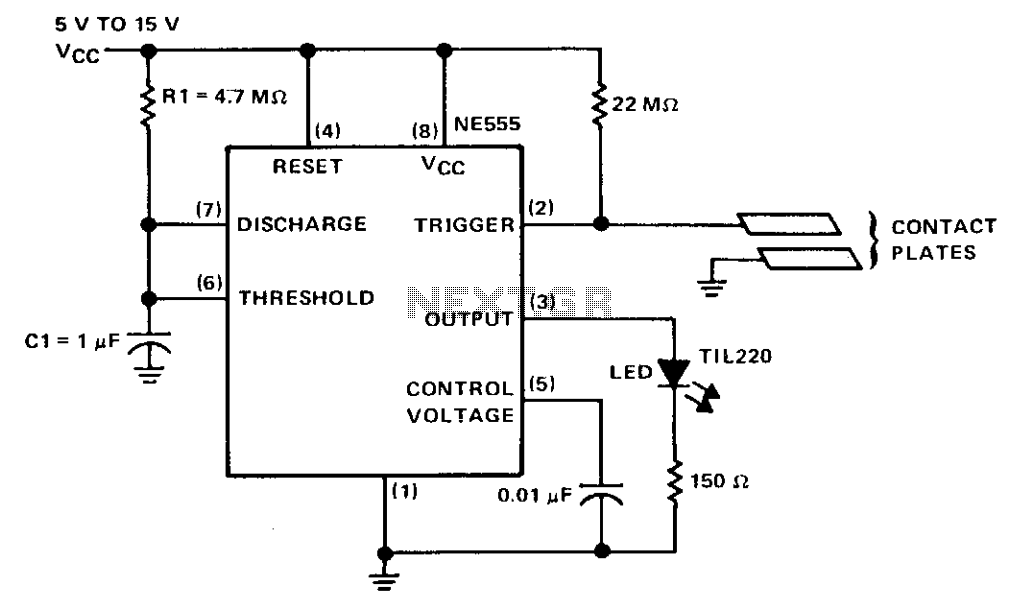
The circuit consists of a NE555 monostable timer, with a unique triggering method. The trigger input is held at a high voltage level by a 22-ohm resistor. When the contact plates are engaged, the operator's skin resistance decreases the...
This is a switching circuit that provides a latching mechanism to create a set of radio buttons using push buttons. This circuit consists of an interlocking circuit. The switching circuit operates on the principle of latching, allowing multiple push buttons...

4 Channel 433MHz Wireless RF Remote Control Kit with a range of 200 meters. This RF remote control offers an extended range of up to 200 meters (650 feet) and is versatile for controlling various devices. The 4 Channel 433MHz...
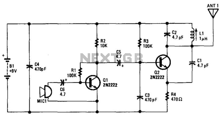
Q1 amplifies the output from an electret microphone (MIC1). The audio signal is fed into oscillator Q2, which modulates the signal. Additionally, L1 and C1 form a tank circuit designed for operation in the 88-MHz frequency range. The antenna...
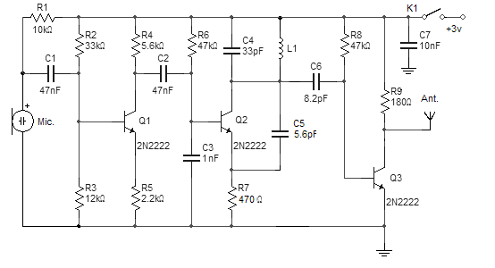
This FM wireless microphone is straightforward to construct and offers significant transmission capabilities, with a range of approximately 300 meters outdoors. Its compact component count and 3V operating voltage allow it to effectively penetrate multiple floors of an apartment...
Here's a way to get a short range bidirectional RF (Radio Frequency) channel on a microcontroller, using the controller's tristatable I/O pins and on-chip comparator with a few passive components. The range with the firmware and simple I came...
Warning: include(partials/cookie-banner.php): Failed to open stream: Permission denied in /var/www/html/nextgr/view-circuit.php on line 713
Warning: include(): Failed opening 'partials/cookie-banner.php' for inclusion (include_path='.:/usr/share/php') in /var/www/html/nextgr/view-circuit.php on line 713