
Am demodulator
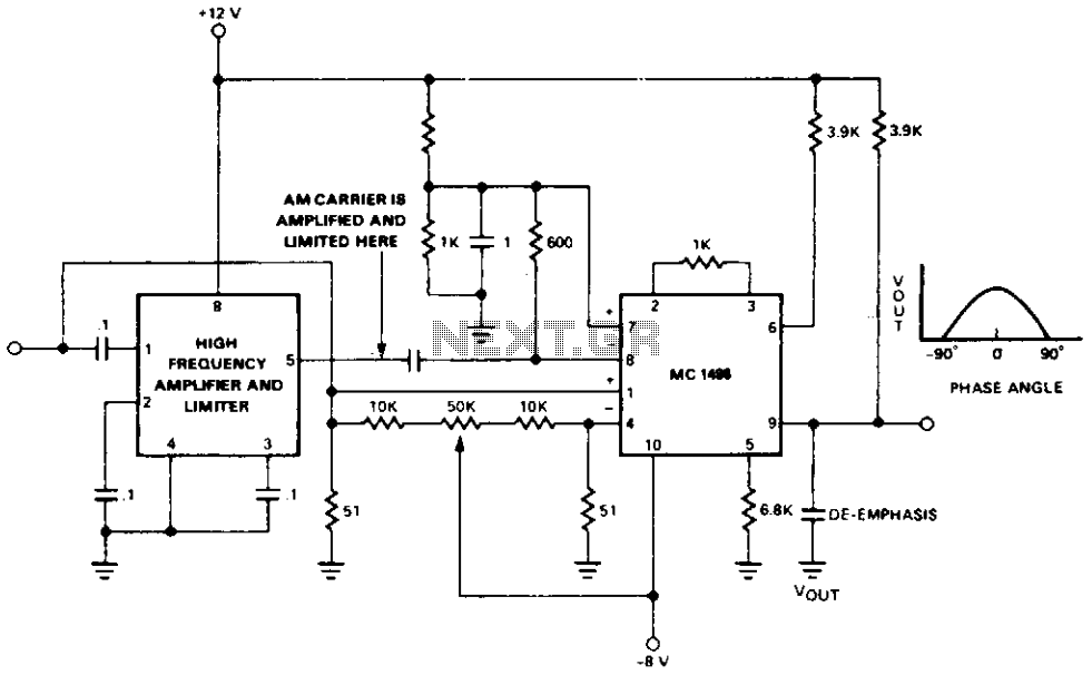
Maximum conversion gain is attained when the carrier signals are in phase, as indicated by the phase-gain relationship. Output filtering is also required to eliminate high-frequency sum components of the carrier from the audio signal.
The described circuit employs an Intermediate Frequency (IF) gain block that plays a crucial role in the amplification and limitation of the AM carrier signal. The specified gain of 55 dB ensures that the signal is sufficiently amplified for further processing. The limiting feature, set at 40 µV, is critical in preventing signal overload, which can lead to distortion and degradation of audio quality.
Once the carrier is amplified and limited, it is routed to the detector at the designated carrier ports. This arrangement allows for effective switching functions, which are essential in various applications, including radio receivers and communication systems. The synchronous AM demodulator (model 1496) is employed to demodulate the signal, taking advantage of its balanced architecture to attenuate the carrier frequency effectively. This design minimizes unwanted artifacts in the output signal, ensuring a cleaner audio output.
To maintain audio fidelity, it is imperative to monitor the input levels to avoid overdriving, which can introduce distortion that adversely affects the quality of the recorded audio. The relationship between phase and gain is critical; maximum conversion gain occurs when the carrier signals are aligned in phase, which enhances the overall efficiency of the demodulation process.
Additionally, output filtering is a necessary step to remove any high-frequency components that may arise from the mixing process, specifically the sum frequencies of the carrier. This filtering ensures that only the desired audio signal is present at the output, further enhancing the clarity and quality of the demodulated audio. Proper implementation of these components and considerations is vital for achieving optimal performance in AM signal processing applications.Amplifying and limiting of the AM carrier is accomplished by the if gain block providing 55 dB of gain or higher with a limiting of 40 µ\. The limited carrier is then applied to the detector at the carrier ports to provide the desired switching function.
The signal is then demodulated by the synchronous AM demodulator (1496) where the carrier frequency is attentuated due to the balanced nature of the device. Care must be taken not to overdrive the signal input so that distortion does not appear in the recorded audio.
Maximum conversion gain is reached when the carrier signals are in phase as indicated by the phase-gain relationship. Output filtering is also necessary to remove high frequency sum components of the carrier from the audio signal.
🔗 External reference
Related Circuits
The advantages of synchronous reception of AM signals are well recognized, including high selectivity, linearity of detection, and a lower noise level at the output compared to other reception methods. The circuit diagram is illustrated in Figure 1. The...
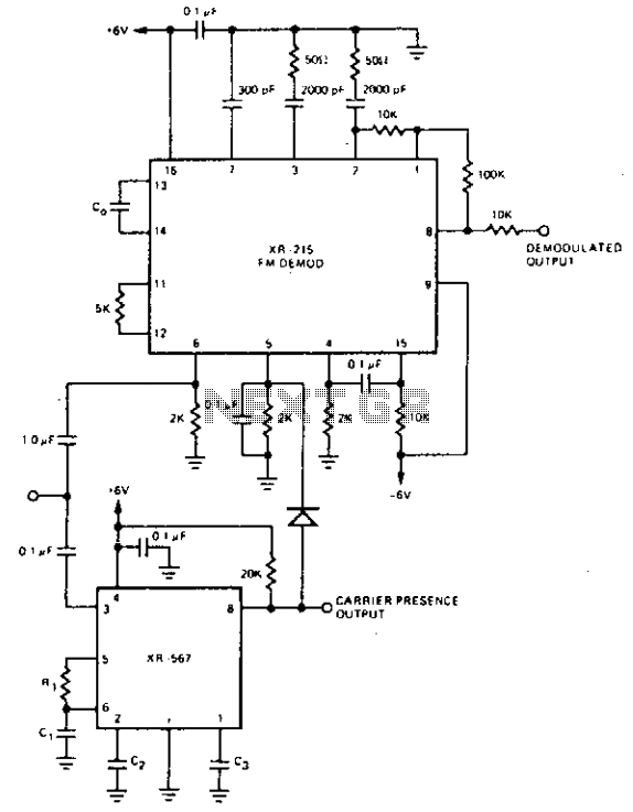
For FM demodulation applications where the bandwidth is less than 10% of the carrier frequency, an XR-J567 can be used to detect the presence of the carrier signal. The output of the XR-567 is used to turn off the...
Construct an accurate LC Meter (Capacitance Inductance Meter) to facilitate the creation of coils and inductors. This LC Meter is capable of measuring very small inductances, making it an ideal tool for various RF coil and inductor applications. The...
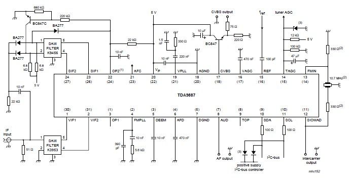
The integrated circuit (IC) is a multistandard vision and sound intermediate frequency (IF) phase-locked loop (PLL) demodulator that operates without the need for alignment. It supports multiple television standards, including PAL, SECAM, and NTSC, and is capable of handling...
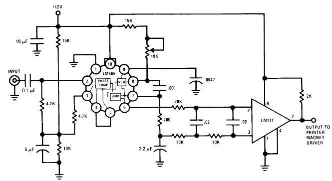
A simple Frequency Shift Keying (FSK) demodulator for 2025 Hz and 2225 Hz can be designed using the LM565, a general-purpose phase-locked loop integrated circuit. This IC includes a stable, highly linear voltage-controlled oscillator that provides low distortion FM...
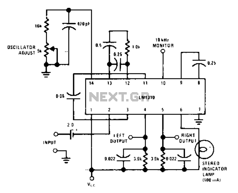
This circuit utilizes a single integrated circuit, the LM1310, to provide left and right outputs from a composite MPX stereo signal. The oscillator adjust resistor R1 is configured for 76 kHz, which corresponds to 19 kHz at pin 10....