
AM Synchronous Demodulator

The circuit design leverages the principles of synchronous detection to achieve enhanced performance in AM signal reception. The synchronized oscillator, which is the heart of the circuit, ensures that the local oscillator frequency is locked to the input signal frequency, enabling precise demodulation of the AM signal. The careful selection of components, such as the specific transistors and tuning elements, contributes to the overall effectiveness of the design. The integration of the AF filter ensures that only the desired audio frequencies are amplified, further improving signal clarity. The use of a resonant tank circuit allows for effective tuning and reception of signals across a specified frequency range, making the circuit suitable for various medium wave applications. The design's ability to maintain stable operation under varying conditions, along with its low power consumption, makes it a viable option for portable or battery-operated devices. Proper assembly and shielding techniques will enhance performance by reducing unwanted interference and noise, ensuring that the received audio signals are of high quality and fidelity.The advantage of synchronous reception of AM signals is widely known. It includes high selectivity, linearity of detection and a low noise level at the output compared to other ways of reception. The circuit diagram is shown in figure 1. The operation of the circuit is based on method of direct locking of the local oscillator frequency by the inpu
t signal. This method has been tested by the author in the medium wave receiver as described in [1], and showed good results. The proposed detector consists of a synchronized oscillator based on the transistors VT1 and VT2, a switching mixer based on the transistor VT3 and an AF filter L2C3C4.
Synchronized oscillator is made on the basis of the oscillator circuit (Fig. 2), proposed by E. Savitsky [2]. The frequency tuning elements C2, R3 and the FET transistor VT1 has been added to this oscillator circuit. When the input signal is applied to the gate of the transistor, the input signal mixing with the signal of the local oscillator in the transistor`s channel.
The component of the base current of the transistor VT2 modulates the signal of the local oscillator frequency, and when the difference frequency becomes equal to the lock range, then the local oscillator switches from the beat mode to the sync mode. This establishes the equality of the input signal frequency and the local oscillator frequency, and the phase difference between voltage of the input signal and the local oscillator † becomes equal to 0 ° or 180 °.
The equality of the frequencies and phases is maintained by the DC component of the base current of VT2, the DC component is proportional to the sin †. As you can see, the device works in the same way as a system PLL, the difference is only in the phase shift, for a PLL system the phase shift is 90 ° in sync mode.
The voltage at the output of the local oscillator has the form of the switching pulses (Fig. 3). This pulses goes to the gate of the transistor VT3, they provide a switching mode of its operation. The voltage envelope of AM signal goes through the AF filter to am audio amplifier. The gain of the detector is 0. 25 times. The local oscillator can be synchronized by a signal with a voltage of hundreds of microvolts. The author conducted an experiment with this detector, in which AM signals of MW band has been received. To do this, a resonant tank circuit tuned to a frequency of MW band has been connected to the the input of the detector circuit, and the demodulated signal was applied to the two-stage audio amplifier [1].
By using the indoor antenna with length of 3 m and the grounding has been received with good quality a signals of a radio stations located at 200. 250 km from the reception site. The coarse adjustment of the local oscillator`s frequency in the range 630. 860 kHz is provided by the potentiometer R3. With the variable capacitor C2 is possible to vary the frequency of the local oscillator within + -15 kHz.
While adjusting the frequency with the resistor R3 the amplitude of the pulses changes. However, it does not drop below 3. 5 V. The cut-off voltage of the transistor KP103J is 0. 5. 2. 2 V, so in the entire operating frequency range of the local oscillator the gain of the detector remains practically unchanged. To expand the dynamic range of the detector and reduce the crosstalk and intermodulation interference it is useful to a resistor in the drain network of the transistor VT3.
This resistor will works as an attenuator. The value of this resistor is chosen based on the specific conditions of reception. The detector is powered by a stabilized and carefully smoothed voltage. The current consumption of the circuit is about 2. 5 mA. The coil L1 is wound on the toroidal ferrite core K7x4x2 600NN (the magnetic permeability is 600), the coil has 52 turns of enameled copper wire of 0. 2 mm (AWG 32) in diameter, the coil has a center tap. It is desirable to shield the coil, for example, wrapp 🔗 External reference
Related Circuits

As the number of stations increased and the power levels also rose, receiver performance had to be enhanced. The pentagrid converter, such as the 6BE6 tube (British EK90 valve), was introduced, which was optimized for mixer performance. This included...
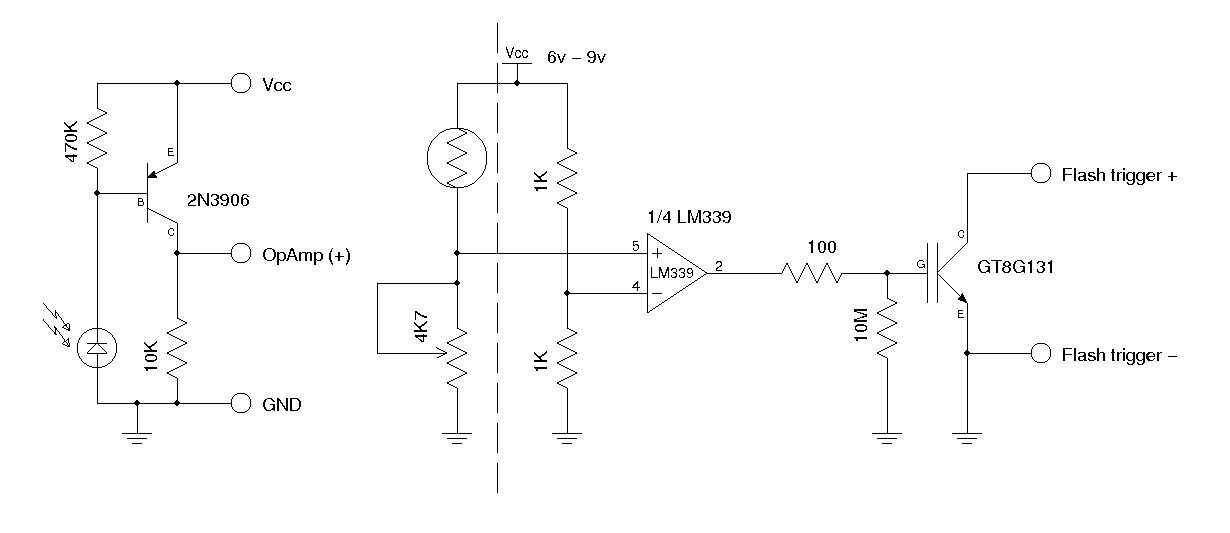
A synchronous camera flash, such as a slave flash, is typically triggered using a silicon-controlled rectifier (SCR). This document presents a circuit designed to trigger a secondary camera flash utilizing an insulated-gate bipolar transistor (IGBT). The use of an...
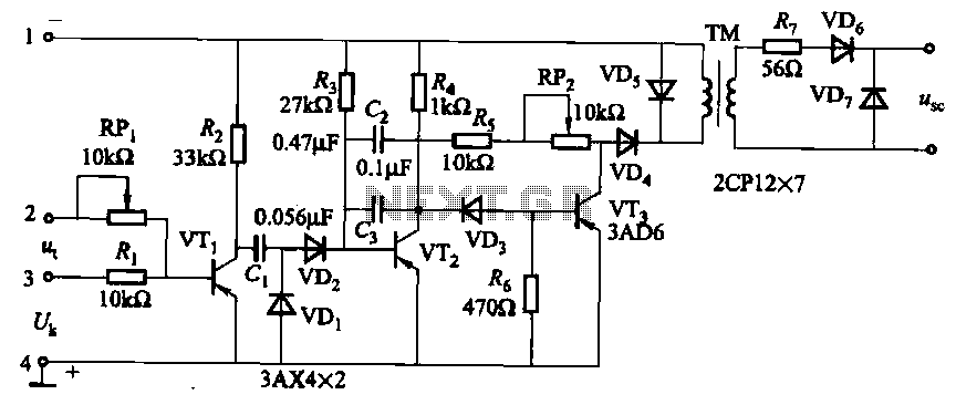
The circuit is designed for inductive loads, specifically within a thyristor power unit, such as a three-phase step-down DC motor speed control and other applications. It is capable of delivering sufficient output power to trigger a thyristor rated at...
Construct an accurate LC Meter (Capacitance Inductance Meter) to facilitate the creation of coils and inductors. This LC Meter is capable of measuring very small inductances, making it an ideal tool for various RF coil and inductor applications. The...

The transition from diodes to synchronous-rectification (SR) MOSFETs in the secondary circuits of flyback converters is increasing with each new generation of MOSFETs, enhancing performance with minimal or no cost increase. SR MOSFETs can offer improved efficiency compared to...
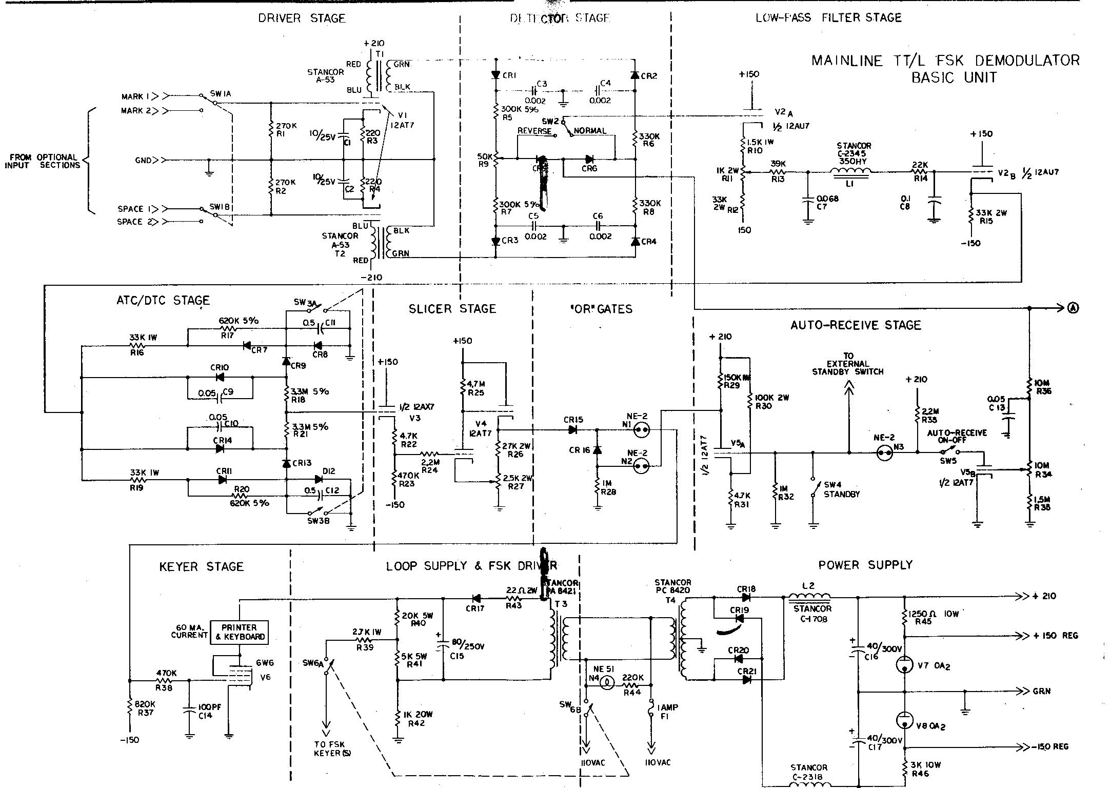
The term "demodulator" is becoming a standard in both commercial and military sectors. "Converters" are often associated with devices that automatically transform Morse code into RTTY, convert 8-level signals to 5-level, or adjust baud rates from 50 to 45,...