
AM LOOP ANTENNAS
An AM loop antenna operates based on electromagnetic induction and resonance principles. The antenna consists of a conductive loop, typically made from copper wire, which serves as the inductor. The size of the loop influences the inductance, while the tuning capacitor, connected in parallel, allows for frequency adjustment. This parallel LC circuit forms a resonant circuit that can be tuned to specific frequencies, enabling the antenna to effectively capture AM radio signals.
The loop's physical dimensions are critical; a larger loop can capture lower frequencies more effectively, while a smaller loop is better suited for higher frequencies. The quality factor (Q) of the loop antenna is important as it determines the selectivity and bandwidth of the signals received. A higher Q indicates a narrower bandwidth, which can improve reception of a specific station but may limit the ability to receive adjacent channels.
To optimize performance, considerations such as the loop's orientation, proximity to obstructions, and the presence of nearby conductive materials should be taken into account. The antenna should ideally be positioned in an open area to minimize interference and maximize signal strength.
Overall, the AM loop antenna exemplifies a simple yet effective design that leverages fundamental electrical principles to achieve reliable radio reception without the need for external power sources.An AM loop antenna is one of the true marvels of electronics. Requiring no power, it takes advantage of the resonant properties of an inductor and a capacitor connected in parallel to receive weak AM stations. The "loop" part of the antenna is the inductor, and the tuning capacitor makes it resonate at a desired frequency.
As a boy in Abilene in 1967, I discovered the basic principle of the loop antenna. By removing a relatively small spiral loop in my five tube table radio, and substituting a much larger loop salvaged from an older radio, I could receive my favorite statio 🔗 External reference
Related Circuits
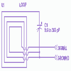
Please find attached your copy of my four foot unamplified box loop. It will tune from 525 kHz to about 1710 kHz covering the entire Broadcast Band. The umbrella stand described in the article is the type you would...
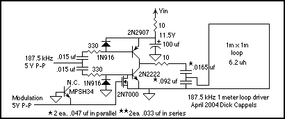
This 1 square meter antenna has radiation resistance of about 10 nanohoms, making the 0.4 Ohm resistance (including skin effect, which about doubled the resistance from the DC value) the dominant loss in the antenna. The lower the resistance,...
NJM2268 is a dual video 6dB amplifier designed for S-VHS VCRs, high-bandwidth VCRs, and similar applications. One channel features a clamp function that stabilizes the DC level of the video signal, while the other channel operates as a bias...
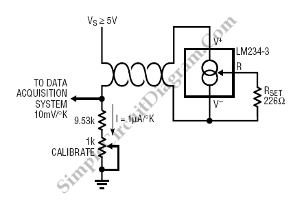
The LM134 is an effective temperature sensor due to its highly linear output characteristic. As a current output device, it remains unaffected by certain environmental factors. The LM134 is a three-terminal device that operates as a current source, providing a...
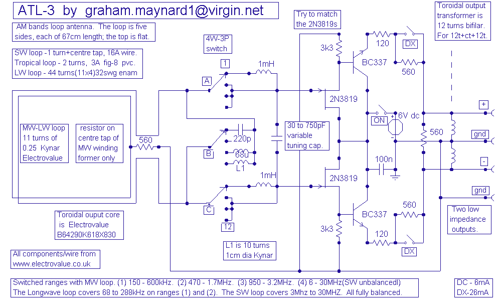
This antenna is the result of long term development and user feedback. All ATL-3 loop windings are centre tapped and balanced w.r.t. their amplifier/receiver chassis ground, and therefore electric field interference pick up tends to self cancel. Magnetic noise...
The circuit diagram represents a brushless DC motor driving circuit designed for a 45V/8A application. It features an open voltage-controlled design that allows for speed adjustment through an external potentiometer connected to a PWM duty cycle. The diagram illustrates...