
am radio receiver with mk484

The MK484 AM radio receiver circuit is designed for optimal performance in receiving amplitude-modulated (AM) signals. The integrated circuit's architecture allows it to efficiently amplify weak radio signals while minimizing noise, making it suitable for various applications, including hobbyist projects and educational demonstrations.
The circuit's power supply configuration is critical; it operates effectively at 1.5V, which is commonly provided by standard AA or AAA batteries. The low current consumption of 0.3mA is particularly advantageous for portable applications, ensuring prolonged battery life and reducing the frequency of battery replacements. This characteristic makes the MK484 ideal for battery-powered AM radio receivers.
The coil L1 plays a vital role in the circuit's performance. The specified 55 turns of 0.315mm enamelled copper wire wound on a ferrite rod enhance the inductance, which is essential for tuning into specific AM frequencies. The choice of wire gauge and the dimensions of the ferrite rod are crucial for achieving the desired inductive properties and resonance characteristics. Proper winding technique is necessary to avoid issues such as uneven inductance or parasitic capacitance, which could degrade the circuit's performance.
In summary, the MK484 AM radio receiver circuit is a compact and efficient design that showcases the capabilities of integrated circuits in radio applications. Its simplicity, combined with high sensitivity and low power consumption, makes it a valuable solution for AM radio reception.Here is a schematic of a good quality AM radio receiver circuit. The heart of the circuit is MK484 AM radio IC. It is a high sensitivity and high quality IC, it has only three leads and comes in TO92 package and require only few external parts because all the necessary circuitry like RF amplifier, AGC and detector are incorporated inside the IC. T he circuit can be operate only on 1. 5V DC and has a very low current consumption only 0. 3mA so the 1. 5 volt battery will last more then hundred hours. Do not give more then 1. 8 volt to the IC. The Coil L1 is equal to 55 turns of 0. 315mm (30 swg) enamelled copper wire wound on 10mm x 100mm long ferrite rod. 🔗 External reference
Related Circuits
A simple CATV upstream fiber optic receiver utilizes DC pilot automatic gain control (AGC). Upstream fiber links in a community antenna television (CATV) system are often challenging to align correctly. Set-top boxes and cable modems use "long-loop" AGC. Additionally,...
The operation of this receiver is analogous to human perception. Humans perceive colors and respond based on what they observe. Similarly, phototransistors react to the intensity of infrared light directed at them. The key distinction is that humans possess...
This article outlines a reliable, straightforward, and universal method for interfacing Motorola mobile radios from the MaxTrac, Radius, and GM300 series with common repeater controllers. The information provided is also relevant for radio interfaces used in IRLP or EchoLink...
Contrary to the beliefs of some radio experimenters, an efficient bipolar regenerative design is achievable. The primary concern lies in the low input impedance of the detector-amplifier bipolar stage. However, this can be effectively compensated for with positive feedback...
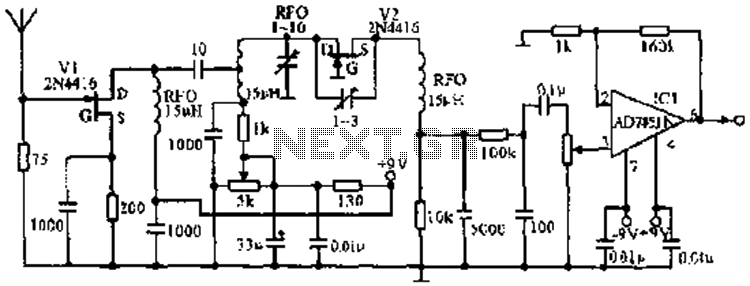
The image illustrates the JFET VHF band super-regenerative receiver circuit. It features high discharge tubes V1 and V2, which serve as the super-regenerative detector tubes. IC1 functions as a low-frequency amplifier. The circuit exhibits a sensitivity of better than...
The most popular network is MED-NET, which encompasses the entire Mediterranean Sea with its observation points. The accompanying map illustrates these observation points. For more information about this network, which is part of the Italian Geophysical National Institute, the...