
infrared ir receiver

The described circuit consists of a 9V battery, an infrared (IR) emitter, a phototransistor, a push button switch, and a red LED. The circuit is designed to demonstrate the principles of infrared communication through binary signaling.
The 9V battery serves as the power source for the entire circuit. The IR emitter, typically an LED that emits infrared light, is connected in series with the push button switch. The push button acts as a control mechanism, allowing the user to activate the IR emitter. When the push button is not pressed, the circuit is open, and the phototransistor remains inactive. As a result, the current flows through the red LED, keeping it illuminated, which indicates a digital '1'.
Once the push button is pressed, the circuit closes, allowing current to flow to the IR emitter. The emitter then produces infrared light, which is detected by the phototransistor. When the phototransistor receives this infrared light, it transitions to its conductive state, diverting the current away from the red LED, which subsequently turns off. This state represents a digital '0'.
This simple yet effective circuit provides a clear visualization of how binary data is transmitted wirelessly using infrared technology. The transition between the red LED being on and off serves as a practical demonstration of the fundamental principles of digital communication, showcasing the role of the IR emitter and phototransistor in interpreting and transmitting binary signals.The way that this receiver works is very similar to the way that we as humans beings work. We see colors and we act depending on the different things seen. The phototransistors does the same thing, if reacts depending upon the intensity of infrared light being shined at it. The real difference between the two parallels seen above is that we humans already have a brain to interpret the different wave lenghts of color, where the infrared LED and phototransistor need some `intelligent` circuitry in order to know what to do when certain data is transmitted. If you`re still a little lost as to how information in the form of 0`s and 1`s can be transmitted using the IR emitter and phototransistor pair, here`s a quick circuit you can build that make make things more clear: Here`s how the circuit above works: The 9v battery is hooked up to both the IR Emitter and Phototransistor.
The IR Emitter, however, is never turned on unless you press the push button. Since the emitter is not powered on, the phototransistor won`t allow current to flow through it, so current will instead flow through the red LED. This means until you press the push button, the red LED remains on. After you press the push button, the emitter shines brightly at the phototransistor and the red LED turns off.
Here`s a video of this circuit in action: This should give you a much better visual of how digital 0`s and 1`s can be transmitted wirelessly using these two infrared components. When the red LED shines, you can see a digital 1. When we press the push button and the red LED turns off, that would be a 0. 🔗 External reference
Related Circuits
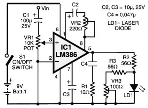
Laser communication system circuit diagram. The circuit module consists of a transmitter and a receiver that utilize the IC LM386. It is powered by a 9V battery. The laser communication system is designed to facilitate wireless data transmission using modulated...
This is the latest version of the Improved Infrared Receiver with Status LED which can control any desktop PC with an ordinary remote control. The project comes along with a small PCB in order to save space. It connects...
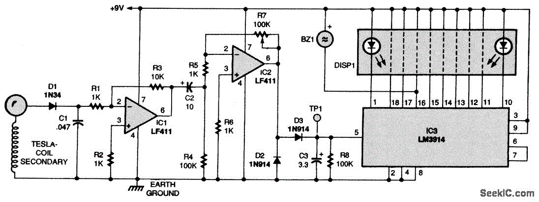
Here is a Tesla coil secondary design: Wind 750 turns of 24-gauge enameled magnet wire onto an 18-inch long piece of 1.9-inch outer-diameter PVC pipe. The large coil has an inductance of approximately 2800 mH and a self-capacitance of...
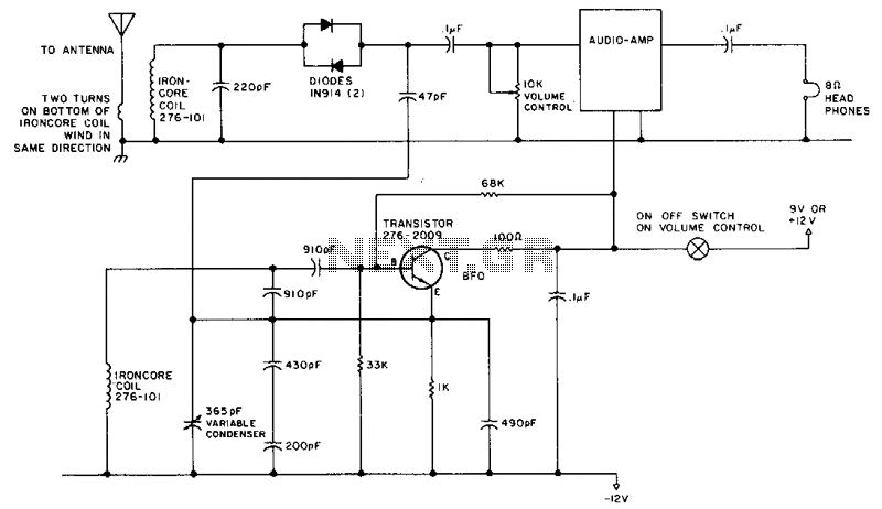
This circuit is designed for operation in the 80m band. It utilizes a 365-pF variable capacitor, specifically intended for the broadcast band, which should be equipped with a vernier drive featuring a six-to-one tuning ratio. This configuration enhances the...
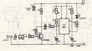
This infrared transmitter utilizes pulse width modulation (PWM). The transmitter is equipped with an LM567 tone decoder circuit. An audio signal (at least 50 mV peak-to-peak) is amplified with transistor T1 and subsequently used to modulate IC1. The frequency...
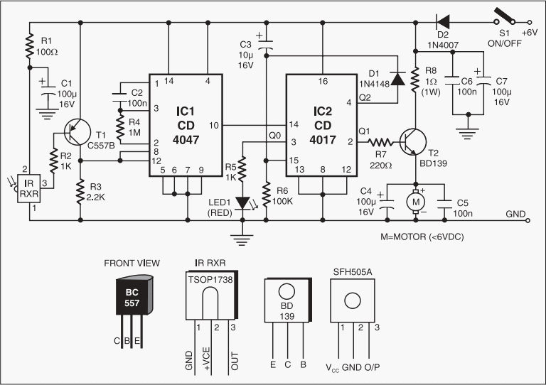
This add-on circuit enables remote switching on and off of battery-operated toy cars using a TV or video remote control handset that operates at 30 to 40 kHz. When powered by a 6V battery, the decade counter CD4017 (IC2),...