
am transmitter double side band
The AM transmitter circuit operates by modulating the audio signal onto a carrier wave, which is subsequently filtered to enhance transmission efficiency. The use of an Op Amp (IC741) allows for high-quality audio amplification, ensuring that the input signal from the microphone is sufficiently strong for effective modulation. The double balanced modulator (DBM) plays a crucial role in suppressing the carrier frequency, thus allowing for the transmission of only the sidebands, which contain the information. This technique improves the power efficiency of the transmitter, as the majority of the power is directed towards the sidebands.
The carrier generation is accomplished using a crystal oscillator, which provides stability and accuracy in frequency. The configuration of the BC548 transistor as a carrier oscillator ensures that the generated signal is clean and suitable for modulation. The subsequent amplification by T1 not only strengthens the carrier signal but also isolates the oscillator from the modulator, preventing any interference that may arise from loading effects.
In terms of operational flexibility, the ability to switch between different crystals allows for easy frequency adjustments, catering to various amateur radio bands. The incorporation of a variable resistor for modulation control enables fine-tuning of the output signal, accommodating different transmission requirements.
The choice of antenna significantly impacts the range and quality of the transmitted signal. A horizontal dipole is favored for its simplicity and effectiveness in the desired frequency range. The recommended 20-meter length for the dipole at 7 MHz ensures optimal performance, while the use of a 75-ohm coaxial cable minimizes signal loss during transmission.
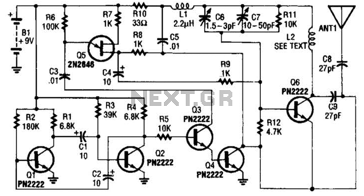
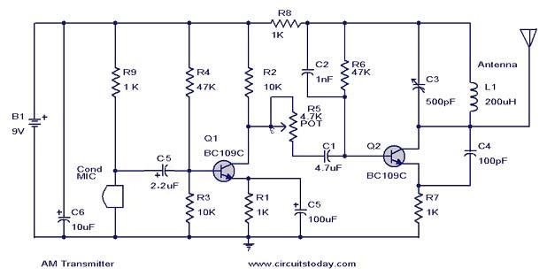
Overall, this AM transmitter circuit is a robust solution for amateur radio enthusiasts seeking to explore amplitude modulation and DSB transmission techniques, with provisions for power amplification and frequency versatility.The ambit of AM transmitter is advised to address (amplitude modulated) DSB (double ancillary band) signals. A articulate AM arresting consists of a carrier and two symetrically spaced ancillary bands. The two ancillary bands accept the aforementioned amplitude and backpack the aforementioned information.
In fact, the carrier itself coveys or carr ies no information. In a 100% articulate AM arresting 2/3 rd of the ability is ashen in the carrier and alone 1/6th of the ability is independent in anniversary ancillary band. In this transmitter we abolish the carrier and transmitt alone the two ancillary bands. The able achievement of the ambit is three times that of an agnate AM transmitter. Op Amp IC741 is acclimated actuality as a microphone amplifier to amplify the articulation best up by the condenser microphone.
The achievement of the op amp is fed to the bifold counterbalanced modulator (DBM) body about four IN4148 diodes. The accentuation akin can be adapted with the advice of preset VR1. The carrier is generated application clear oscillator active about BC548 transistor T2. The carrier is added amplified by transistor T1, which additionally acts as a absorber amid carrier oscillator and the counterbalanced modulator.
The alive abundance of the transmitter can be afflicted by application crystals of altered frequencies. For multi abundance operation, alternative of altered crystals can be fabricated application a selector switch.
Ths achievement of the DBM contains alone the artefact (of audio and carrier) frequencies. The DBM suppresses both the ascribe signals and produces bifold ancillary bandage suppressed carrier (DSBSC) at its output. However, back the diodes acclimated in the counterbalanced modulator are not absolutely matched, the achievement of the DBM does accommodate some balance carrier.
This is accepted as carrier leakage. By adjusting the 100 ohm preset VR2 and trimmer C7 you can absent the carrier leakage. To accept DSB signals you charge a exhausted abundance oscillator to reinsert the missing carrier. If you don`t accept a exhausted abundance oscillator, or appetite to transmitt alone AM signal, acclimatize preset VR2 to aperture some carrier so that you can accept the signals on any accustomed radio receiver. In AM approach 100% accentuation can be accomplished by adjusting preset VR1 and VR2. Range of the circuit depends on the type of antenna used. It is very important to use matched antenna to radiate the signals effectively. I used horizontal dipole antenna, which is simple and easy to construct. For 7 MHz, ie 40 meter ham band the length of dipole antenna will be 20 meter. Use 75 Ohms co-axial cable to connect antenna and transmitter. I was able to get 57 report from station 80 kilometer away. You can easily add a Linear RF amplifier using IRF830 to get more power. 🔗 External reference
Related Circuits
The transmitter utilizes a 6BW6 vacuum tube to achieve an output power of approximately 5 watts. The circuit includes a component CI that is calibrated to produce the cleanest continuous wave (CW) note. The tuning capacitors C8 and C9...
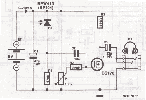
This wireless headphones transmitter ensures quality reception over a distance of 2 meters. The oscillator frequency ranges from 1750 kHz to 3500 kHz, and for the antenna, it... The wireless headphones transmitter operates within a frequency range of 1750 kHz...
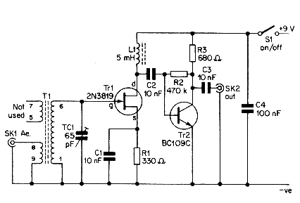
This simple aerial booster circuit design could serve as an alternative or a hobby project for creating an aerial booster device for Citizen Band (CB) radio. The aerial booster circuit is designed to enhance the performance of Citizen Band (CB)...
This document presents a circuit diagram of a simple AM transmitter that is capable of transmitting audio signals to a specified area. The circuit is designed with a limited power output to comply with FCC regulations while effectively producing...

A composite stereo signal, as transmitted by FM radio stations, is composed of at least three parts: A base band mono signal, a double sideband channel difference signal, and a pilot carrier. The signal composition is somewhat analogous to...
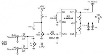
The FM transmitter circuit is built using a single MAX2606 chip. This simple FM transmitter connects a home entertainment system to a portable radio, allowing music to be played in one room and listened to in another, such as...
Warning: include(partials/cookie-banner.php): Failed to open stream: Permission denied in /var/www/html/nextgr/view-circuit.php on line 713
Warning: include(): Failed opening 'partials/cookie-banner.php' for inclusion (include_path='.:/usr/share/php') in /var/www/html/nextgr/view-circuit.php on line 713