
Ambisonic Pan-Rotate
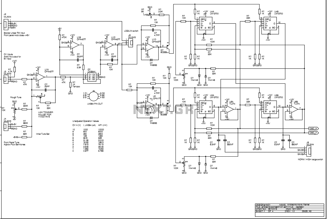
LM13700 VCAs are used in a configuration identical to that shown in the Nat Semi data sheet that produces minimal distortion. It is not perfect but then VCAs never are. Two VCAs are used in inverse polarity for each of the X and Y multiplier sections to guarantee zero output for zero control current. This ensures that change of control voltage amplitude will only result in increased gain and not an imbalance in the B format signal. (This could happen if one VCA was used as a four quadrant multiplier) The reversible quadrature oscillator from the frequency shifter project is used to provide the sine-cosine control voltages for automatic rotation of the output signal. An X-Y joystick with circular outer restraint is used to provide manual sine-cosine voltages for manual signal rotation.
Controls and Inputs: Mono to B-format Section
Mono source input: 1/4 inch jack unbalanced mono
B format output: 5-pin XLR unbalanced
LOG CV input: 1/4 inch jack mono
LOG manual control: ordinary pot
LIN CV input: 1/4 inch jack mono
LIN manual control: ordinary pot
Oscillator LOG/LIN switch: toggle
Oscillator range switch: toggle
Oscillator direction switch: toggle
Joystick - oscillator select
Pan-rotate control: joystick
Pan-rotate CV input: 1/4 inch jack stereo, shield GND, X control ring, Y control tip, +/- 1V
The rotate mode switch is set to oscillator. The ACW-CW switch is set in either position depending on the clockwise/anti-clockwise sense of rotation required. In this mode, the sound is continually panned around the soundstage at a frequency set by the oscillator. For conventional operation, the oscillator will be set to the LOW position for slow rotation. In the HIGH position, the sound will be spun around at audio frequency so that unusual rotation-modulation effects can be created. The oscillator has two modes of control, those being LOG or LIN. In the LOG mode, the direction is set solely by the ACW-CW switch, and the speed is set in a logarithmic sense by the manual LOG control. Alternatively, the oscillator can be controlled in this mode by an input voltage which obeys the 1V/octave synth control law. The voltage is fed into the LOG CV input which overrides the manual setting control. This gives the potential to create unusual synth sounds. The fine-tune control allows setting for 5V CV = A440.
In the LIN mode, the direction of rotation is controlled by both the ACW-CW switch and the LIN control. In the center position, the LIN control gives zero rotation. Provided that the ACW-CW switch is in the CW position, turning the control clockwise will start the sound rotating in the CW direction, and turning the control anti-clockwise will start rotation in the ACW direction. Changing the ACW-CW position changes this direction. Control of the frequency on this control is linear in nature. This mode can also be controlled by an input voltage fed into the LIN CV input. A +5V input is equivalent to advancing the manual control fully clockwise, and a -5V input fully anti-clockwise.
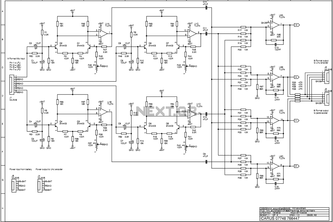
The circuit employs two LM13700 voltage-controlled amplifiers (VCAs) configured in a differential arrangement to achieve minimal distortion and maintain signal integrity. The inverse polarity configuration of the VCAs ensures that any control current applied results in a balanced output, which is critical for maintaining the integrity of the B format signal. The integration of a quadrature oscillator allows for automatic modulation of the output signal, providing flexibility in signal rotation. Manual control is facilitated through an X-Y joystick, enabling user-defined sine-cosine voltage outputs that directly influence the modulation characteristics.
The input section is designed to accommodate various control signals, with dedicated jacks for mono input and control voltage inputs. The use of standard 1/4 inch jacks ensures compatibility with a wide range of audio equipment. The B format output is provided through a 5-pin XLR connector, which is standard in professional audio applications.
The oscillator's operational modes (LOG and LIN) offer distinct control characteristics, enabling both logarithmic and linear frequency modulation. The toggle switches for mode selection and direction provide intuitive user interaction, allowing for real-time adjustments to the sound output. The joystick pan-rotate control adds an additional layer of user engagement, allowing for dynamic modulation of the output signal in a live performance setting.
Overall, this circuit design emphasizes versatility and control, making it suitable for a variety of audio applications, including synthesizers and effects processors. Its thoughtful integration of components and user controls provides a robust platform for creative sound manipulation.LM13700 VCAs are used in a configuration identical to that shown in the Nat Semi data sheet that produces minimal distortion. It is not perfect but then VCAs never are. Two VCAs are used in inverse polarity for each of the X and Y multiplier sections to guarantee zero output for zero control current.
This ensures that change of control voltage amplitude will only result in increased gain and not an imbalance in the B format signal. (This could happen if one VCA was used as a four quadrant multiplier) The reversible quadrature oscillator from the frequency shifter project is used to provide the sine-cosine control voltages for automatic rotation of the output signal.
An X-Y joystick with circular outer restraint is used to provide manual sine-cosine voltages for manual signal rotation. Controls and Inputs: Mono to B-format Section Mono source input 1/4 inch jack unbalanced mono B format output 5-pin XLR unbalanced LOG CV input 1/4 inch jack mono LOG manual control ordinary pot LIN CV input 1/4 inch jack mono LIN manual control ordinary pot Oscillator LOG/LIN switch toggle Oscillator range switch toggle Oscillator direction switch toggle Joystick - oscillator select Pan-rotate control joystick Pan-rotate CV input, 1/4 inch jack stereo, shield GND, X control ring, Y control tip, +/- 1V The rotate mode switch is set to oscillator. The ACW-CW switch is set in either position depending on the clockwise/anti-clockwise sense of rotation required.
In this mode the sound is continually panned around the soundstage at a frequency set by the oscillator. For conventional operation the oscillator will be set to the LOW position for slow rotation. In the HIGH position the sound will be spun around at audio frequency so that unusual rotation-modulation effects can be created.
The oscillator has two modes of control those being LOG or LIN. In the LOG mode the direction is set solely by the ACW-CW switch and the speed is set in a logarithmic sense by the manual LOG control. Alternatively the oscillator can be controlled in this mode by an input voltage which obeys the 1V/octave synth control law.
The voltage is fed into the LOG CV input which overrides the manual setting control. This gives the potential to create unusual synth sounds. The fine tune control allows setting for 5V CV = A440. In the LIN mode the direction of rotation is controlled by both the ACW-CW switch and the LIN control. In the centre position the LIN control gives zero rotation. Provided that the ACW-CW switch is in the CW position, turning the control clockwise will start the sound rotating in the CW direction and turning the control anti-clockwise will start rotation in the ACW direction.
Changing the ACW-CW position changes this direction. Control of the frequency on this control is linear in nature. This mode can also be controlled by an input voltage fed into the LIN CV input. A +5V input is equivalent to advancing the manual control fully clockwise and a -5V input fully anti-clockwise. 🔗 External reference
Controls and Inputs: Mono to B-format Section
Mono source input: 1/4 inch jack unbalanced mono
B format output: 5-pin XLR unbalanced
LOG CV input: 1/4 inch jack mono
LOG manual control: ordinary pot
LIN CV input: 1/4 inch jack mono
LIN manual control: ordinary pot
Oscillator LOG/LIN switch: toggle
Oscillator range switch: toggle
Oscillator direction switch: toggle
Joystick - oscillator select
Pan-rotate control: joystick
Pan-rotate CV input: 1/4 inch jack stereo, shield GND, X control ring, Y control tip, +/- 1V
The rotate mode switch is set to oscillator. The ACW-CW switch is set in either position depending on the clockwise/anti-clockwise sense of rotation required. In this mode, the sound is continually panned around the soundstage at a frequency set by the oscillator. For conventional operation, the oscillator will be set to the LOW position for slow rotation. In the HIGH position, the sound will be spun around at audio frequency so that unusual rotation-modulation effects can be created. The oscillator has two modes of control, those being LOG or LIN. In the LOG mode, the direction is set solely by the ACW-CW switch, and the speed is set in a logarithmic sense by the manual LOG control. Alternatively, the oscillator can be controlled in this mode by an input voltage which obeys the 1V/octave synth control law. The voltage is fed into the LOG CV input which overrides the manual setting control. This gives the potential to create unusual synth sounds. The fine-tune control allows setting for 5V CV = A440.
In the LIN mode, the direction of rotation is controlled by both the ACW-CW switch and the LIN control. In the center position, the LIN control gives zero rotation. Provided that the ACW-CW switch is in the CW position, turning the control clockwise will start the sound rotating in the CW direction, and turning the control anti-clockwise will start rotation in the ACW direction. Changing the ACW-CW position changes this direction. Control of the frequency on this control is linear in nature. This mode can also be controlled by an input voltage fed into the LIN CV input. A +5V input is equivalent to advancing the manual control fully clockwise, and a -5V input fully anti-clockwise.
The circuit employs two LM13700 voltage-controlled amplifiers (VCAs) configured in a differential arrangement to achieve minimal distortion and maintain signal integrity. The inverse polarity configuration of the VCAs ensures that any control current applied results in a balanced output, which is critical for maintaining the integrity of the B format signal. The integration of a quadrature oscillator allows for automatic modulation of the output signal, providing flexibility in signal rotation. Manual control is facilitated through an X-Y joystick, enabling user-defined sine-cosine voltage outputs that directly influence the modulation characteristics.
The input section is designed to accommodate various control signals, with dedicated jacks for mono input and control voltage inputs. The use of standard 1/4 inch jacks ensures compatibility with a wide range of audio equipment. The B format output is provided through a 5-pin XLR connector, which is standard in professional audio applications.
The oscillator's operational modes (LOG and LIN) offer distinct control characteristics, enabling both logarithmic and linear frequency modulation. The toggle switches for mode selection and direction provide intuitive user interaction, allowing for real-time adjustments to the sound output. The joystick pan-rotate control adds an additional layer of user engagement, allowing for dynamic modulation of the output signal in a live performance setting.
Overall, this circuit design emphasizes versatility and control, making it suitable for a variety of audio applications, including synthesizers and effects processors. Its thoughtful integration of components and user controls provides a robust platform for creative sound manipulation.LM13700 VCAs are used in a configuration identical to that shown in the Nat Semi data sheet that produces minimal distortion. It is not perfect but then VCAs never are. Two VCAs are used in inverse polarity for each of the X and Y multiplier sections to guarantee zero output for zero control current.
This ensures that change of control voltage amplitude will only result in increased gain and not an imbalance in the B format signal. (This could happen if one VCA was used as a four quadrant multiplier) The reversible quadrature oscillator from the frequency shifter project is used to provide the sine-cosine control voltages for automatic rotation of the output signal.
An X-Y joystick with circular outer restraint is used to provide manual sine-cosine voltages for manual signal rotation. Controls and Inputs: Mono to B-format Section Mono source input 1/4 inch jack unbalanced mono B format output 5-pin XLR unbalanced LOG CV input 1/4 inch jack mono LOG manual control ordinary pot LIN CV input 1/4 inch jack mono LIN manual control ordinary pot Oscillator LOG/LIN switch toggle Oscillator range switch toggle Oscillator direction switch toggle Joystick - oscillator select Pan-rotate control joystick Pan-rotate CV input, 1/4 inch jack stereo, shield GND, X control ring, Y control tip, +/- 1V The rotate mode switch is set to oscillator. The ACW-CW switch is set in either position depending on the clockwise/anti-clockwise sense of rotation required.
In this mode the sound is continually panned around the soundstage at a frequency set by the oscillator. For conventional operation the oscillator will be set to the LOW position for slow rotation. In the HIGH position the sound will be spun around at audio frequency so that unusual rotation-modulation effects can be created.
The oscillator has two modes of control those being LOG or LIN. In the LOG mode the direction is set solely by the ACW-CW switch and the speed is set in a logarithmic sense by the manual LOG control. Alternatively the oscillator can be controlled in this mode by an input voltage which obeys the 1V/octave synth control law.
The voltage is fed into the LOG CV input which overrides the manual setting control. This gives the potential to create unusual synth sounds. The fine tune control allows setting for 5V CV = A440. In the LIN mode the direction of rotation is controlled by both the ACW-CW switch and the LIN control. In the centre position the LIN control gives zero rotation. Provided that the ACW-CW switch is in the CW position, turning the control clockwise will start the sound rotating in the CW direction and turning the control anti-clockwise will start rotation in the ACW direction.
Changing the ACW-CW position changes this direction. Control of the frequency on this control is linear in nature. This mode can also be controlled by an input voltage fed into the LIN CV input. A +5V input is equivalent to advancing the manual control fully clockwise and a -5V input fully anti-clockwise. 🔗 External reference
Related Circuits
A three-dimensional surround sound Ambisonic recording can be captured using a tetrahedrally arranged quartet of cardioid pattern microphone capsules connected to some simple circuitry to convert the outputs to a standard B-format signal. B-format signals represent a 3D soundfield...
The decoder is intended to be a reference quality prototype with maximum flexibility for experimental use with different speaker layouts. A new improved version has been added at the end. There are two main sections to the instrument. The...