
UHJ Ambisonic Decoder
1) The switches used for the distance compensation are not very good for audio signals. The contacts and wipers are not gold plated and poor audio connections have developed across these switches used in another application after only a few months of light usage. This can be very annoying in used, as channels cut in and out at random and the switches need to be given a hearty wiggle to get the contacts wiped and reconnected.
2) In practical use, the conditions in the room change the perceived loudness of each speaker and the dial-in settings are not the most suitable. I found that setting up the speaker balance by playing back Ambisonic and stereo material gave better results in a real room, so the accurate steps are not needed. It would be an improvement and cost reduction to simply replace these switches and resistors with plain old audio pots, or not have them at all and to rely on level pots which are usually available on whatever speaker amps are being used.
The quadrant and 9 degree angle controls are very awkward to use in practice. Having used the decoder, 9 degrees is far too fine a graduation to notice in practice and having to figure out which quadrant the speaker is in every time is clumsy and confusing, especially as the speaker can be correctly set in two different quadrant settings if directly at the font, back, left or right positions, using 0 or 90 degree angle settings. Confusing.
A better way to do this would be to use a 12 position switch to simply dial in the angle of the speaker in a more intuitive way, with the fully anticlockwise switch position being the directly rear 6 o'clock speaker position and fully clockwise being the slightly to the right rear 5 o'clock position. The switch can be a simple, cheap, 12 way switch which drives on-board electronic switches in the appropriate way to give the correct output. This will save on audio wiring to the front panel. A 12 way switch would be nice, as the positions of the clock would be a natural way to describe the angle of the speaker position. Also, the cheap 12-way rotary switches available have 30 degree steps and a 30 degree angle between the two end stop positions, and so perfectly indicate the actual speaker location on the front panel.
The circuit design features a dual board architecture, with the UHJ decoder board (amb02) and the B format decoder board (amb01). The UHJ board accepts stereo UHJ signals through two standard domestic phono sockets, converting them into a B format signal, which is then passed to the B format decoder board. The B format board generates the necessary audio outputs for each speaker, accommodating both inputs from the UHJ decoder and external B format sources via a female 5-pin XLR connector.
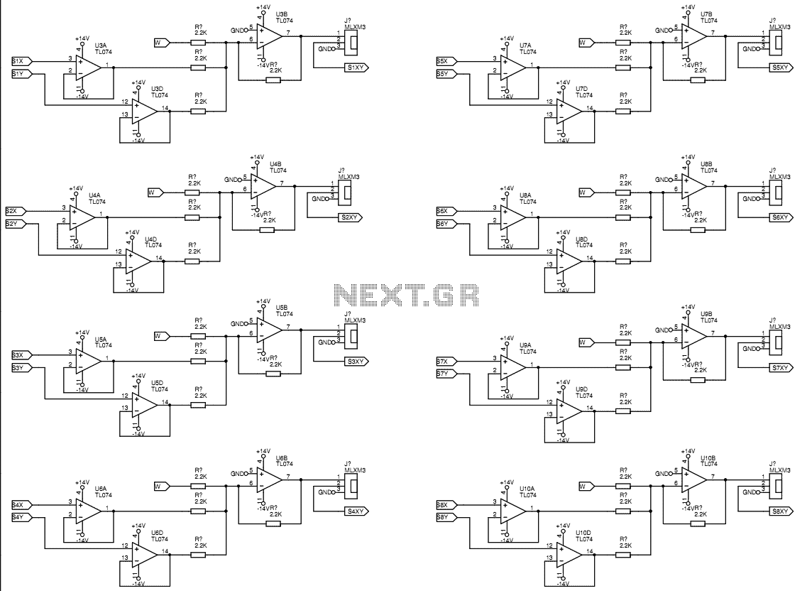
The circuit employs Texas TL074 quad op-amps for audio processing, which are known for their good performance-to-cost ratio. The design omits shelf filters and phase distance compensation, focusing instead on amplitude distance compensation adjustable in 2dB increments for each speaker. The voltage regulation is designed for approximately ±14V, allowing for efficient operation with a 12V transformer while minimizing power dissipation.
Signal processing includes buffering and amplification of the W signal, followed by the generation of unity gain buffered and inverted versions of the X and Y signals. These signals are conditioned for later stages through appropriate weighting and polarity adjustments controlled via front panel switches.
The design acknowledges practical usability issues with the speaker amplitude balancing pots and angle controls, proposing improvements such as replacing unreliable switches with audio pots and adopting a more intuitive method for angle selection through a 12-position switch. This would enhance user experience and simplify the setup process in real-world applications, ensuring more consistent performance in various acoustic environments.The decoder is intended to be a reference quality prototype with maximum flexibility for experimental use with different speaker layouts. A new improved version has been added at the end. There are two main sections to the instrument. The UHJ decoder board, amb02 accepts 'stereo' UHJ sources and converts them to B format. The B format decoder board, amb01 generates the audio signals for each speaker from the B format signal.
This B format input signal can come either from the UHJ decoder or from a separate B format source. The stereo UHJ signal enters on two domestic phono sockets. The decoded B format output is on a 5 pin male XLR which conforms to the pin assignment used on the historic Audio and Design Ambisonic units. The B format input to the B format decoder is a female 5-pin XLR. Finally, the outputs to the amplifiers are once more on domestic phono sockets. The decoder deals only with horizontal surround. The Z signal is ignored. The Texas TL074 quad op-amp is used extensively, as it is a good audio performer while being cheap. Shelf filters are not included. Shelf filtering alters the spectral content of the W signal relative to the X and Y signals to compensate for the blocking effect that the head has on the right ear when a sound comes from the left direction. The degree of filtering is different for different speaker layouts, making it difficult to apply in a generalised decoder like this one.
Phase distance compensation is not included in this decoder either. Phase distance compensation attempts to make the wavefronts more spherical in some way by applying a phase equalisation at a very low frequency. Once more I elected to omit this feature as it seemed to be a very small finessing of the system, and again is dependant on speaker layout.
Amplitude distance compensation is available for each speaker in steps of 2dB. This sheet shows the voltage regulators which are standard. Approximately ±14V is chosen for the voltage rails as this allows the use of a 12V transformer. There is about 4V drop available to the regulators which lets them stay well out of drop-out without dissipating too much power. The B format input enters the board from the rear panel XLR onto a six pin header. The W signal is buffered and amplified by root 2 at this point so that it is at the correct level for simple equality gain summing in later stages.
X and Y are unity gain buffered and inverted versions are created. This gives ±X and ±Y signals for selection by the later switching stages. The X and Y signals leave the sheet and have the appropriate SIN/COS weight and polarity selected by the front panel switches. The signals return on the same connectors and are summed on amb01-02.sch. To use the speaker amplitude balancing pots it is possible to measure the distance from the listener to each speaker and "dial-in" an accurate compensation on these rotary switches, but this has problems.
1) The switches used for the distance compensation are not very good for audio signals. The contacts and wipers are not gold plated and poor audio connections have developed across these switches used in another application after only a few months of light usage. This can be very annoying in used, as channels cut in and out at random and the switches need to be given a hearty wiggle to get the contacts wiped and reconnected.
2) In practical use, the conditions in the room change the perceived loudness of each speaker and the dial-in settings are not the most suitable. I found that setting up the speaker balance by playing back Ambisonic and stereo material gave better results in a real room, so the accurate steps are not needed.
It would be an improvement and cost reduction to simply replace these switches and resistors with plain old audio pots, or not have them at all and to rely on level pots which are usually available on whatever speaker amps are being used. The quadrant and 9 degree angle controls are very awkward to use in practice. Having used the decoder, 9 degrees is far too fine a graduation to notice in practice and having to figure out which quadrant the speaker is in every time is clumsy and confusing, especially as the speaker can be correctly set in two different quadrant settings if directly at the font, back, left or right positions, using 0 or 90 degree angle settings.
Confusing. A better way to do this would be to use a 12 position switch to simply dial in the angle of the speaker in a more intuitive way, with the fully anticlockwise switch position being the directly rear 6 o'clock speaker position and fully clockwise being the slightly to the right rear 5 o'clock position. The switch can be a simple, cheap, 12 way switch which drives on-board electronic switches in the appropriate way to give the correct output.
This will save on audio wiring to the front panel. A 12 way switch would be nice, as the positions of the clock would be a natural way to describe the angle of the speaker position. Also, the cheap 12-way rotary switches available have 30 degree steps and a 30 degree angle between the two end stop positions, and so perfectly indicate the actual speaker location on the front panel.
🔗 External reference
Related Circuits
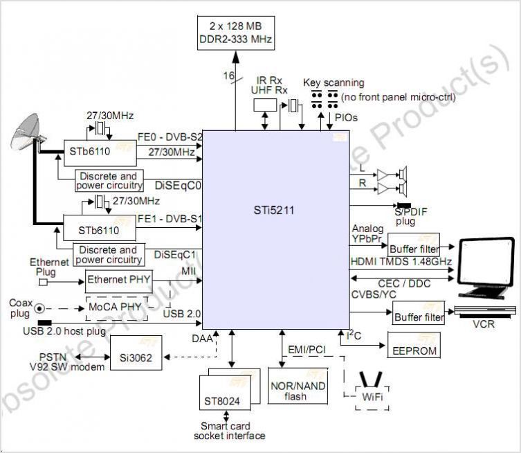
The STI7167 utilizes advanced process technology to deliver a fully featured HD AVC DVB-C and DVB-T demodulator and decoder integrated circuit (IC). This highly integrated system-on-chip is designed for set-top box (STB) markets across cable, terrestrial, and terrestrial/IP hybrid...
Surround Sound Decoder circuit diagram. The circuit's operation begins when the stereo sound signal carries surround sound information through the master volume section. This drives the Left channel (Lch), which is connected to Model TL072 IC1A and IC1B, with...
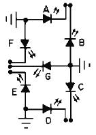
Observe that the output letters of the integrated circuit [Output A] correspond with the diode letters in the 7-segment LED display above. Each output of the integrated circuit corresponds to a specific input [diode] of the seven-segment display. 1....
Creating a universal remote control system has become quite straightforward. One can acquire the necessary chips, assemble them, and the high-tech remote control device will be operational. This document discusses specific remote control chips designed for this purpose. The...
The circuit amplifier and attenuator control video detector consists of a composition for the synchronization channel. The synchronization interval is where the gain circuit is increased. The described circuit involves an amplifier and an attenuator that work together to control...
This surround-sound decoder is based on the "Hafler" principle, first discovered by David Hafler in the early 1970s. The original idea was to connect a pair of speakers for use as rear speakers in a surround setup. While this...