
analog line follower robot
The line follower robot operates based on a simple yet effective design that utilizes analog components instead of a microcontroller for control. The photodiode acts as the primary sensor, detecting the presence of light reflected from the track. This light detection is crucial for determining the robot's position relative to the line it is following. The LED provides the necessary illumination for the photodiode, ensuring reliable operation even in varying ambient light conditions.
The comparator, implemented with the LM324, plays a vital role in processing the signals from the photodiode. By comparing the voltage levels generated by the photodiode under different lighting conditions, the comparator can determine whether the robot is on the line or off it. The output from the LM324 is used to control the driver circuit, which consists of transistors configured to manage the direction and speed of the DC motors.
In the driver circuit, the transistors act as electronic switches that enable or disable the motors based on the logic levels received from the comparator. The configuration allows for forward and backward movement, enabling the robot to adjust its path dynamically in response to the detected line.
The inclusion of variable resistors allows for calibration of the sensitivity of the sensor circuit, making it adaptable to different line colors and surface materials. This adaptability is essential for ensuring optimal performance in various environments.
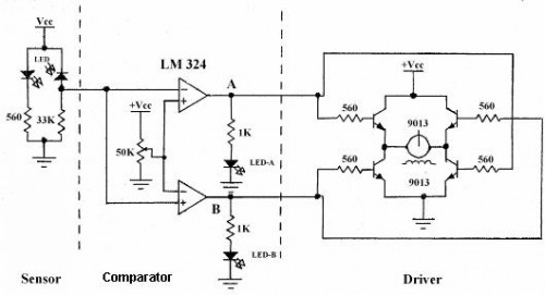
Overall, this line follower robot design exemplifies an efficient and straightforward approach to robotic control, showcasing the potential of analog components in automation and robotics without relying on complex microcontroller systems.Perhaps we often see robots line follower robot which is going to follow the line on the track. in general line follower robot is controlled by a microcontroller, but in this article online follower robots in the design without using the microcontroller. For that you should try to assemble his Line Follower Robot series consists of three main part s, namely the sensor circuit, a comparator (comparison) and a set of drivers work. The following is a schematic drawing line follower robot: Sensor used consists of photo diode. This sensor resistance value will decrease when exposed to light and work on riverse bias conditions. The light sensor is used for LED Superbright, this component has a very bright light, enough to supply the light for the photo diode.
If the photo diode is not exposed to light, then the resistance will be large or can we assume infinite. So that current flows into the comparator is very small or can be assumed to be logic 0 if exposed to light photo diodes, photo diodes will act as a source of voltage and resistance will be small, so there will be currents flowing into the comparator and logic 1.
The following is a schematic line follower robotimage sensor: Comparator in this circuit using the LM 324 IC that contains a series of Op Amp is used to compare the input from sensors. Where will compare the input from the Op Amp IC LM 324 is output to logic high. So no need to draw on the output. This IC can work on range 3 volts to 30 volts and can work with a normal starting voltage 6 volts. In this series there are also 4 LED, which serves as an indicator. To set the voltage in comparison, connected variable resistor (VR) between the two OP Amp IC LM 324. If no current flows from circuit to circuit sensor is input to the circuit voltage is 0 volts, so the voltage at IC terminals 1 (+)> (-), LED-A in, whereas 2-D IC LED off.
If the current flows from circuit to circuit was the voltage sensor input for this circuit near Vcc, so the voltage at IC terminal 2 (+) <(-), LED-B on, whereas the IC 1-LED A off. Conditions between points A and b will always turn around. The following is a schematic drawing line follower robotcomparator: Driver is a circuit consisting of transistors used to drive DC motors.
Where is the main component of the transistor assembled according to the input character in A to logic 1, then the current flows in the circuit, consequently the transistor 1 and 4 on that basis, the bias, so that the motor rotates. So that when input A logic 1 is input to logic B 0, so the transistor 2 and 3 will be turned off. In logic inputs B 1, then the current flows in the circuit, consequently the transistor 2 and 3 on the basis of bias, so that the motor spinning, but in the opposite direction.
The following is a schematic drawing line follower robot motor driver: 🔗 External reference
Related Circuits
The AD7781 is a complete low-power front-end solution for bridge sensor products, including weigh scales, strain gauges, and pressure sensors. It contains a precision low-power 20-bit sigma-delta ADC, an on-chip low-noise programmable gain amplifier (PGA), and an on-chip oscillator....
Mixed Analog/Digital Design Using Split Power and Ground Planes. The following example illustrates the design of a circuit that incorporates both analog and digital components. It features multiple power planes and a single ground plane that is divided into...
This is a nice design for people who have no tachometer in the car or on the bike. The circuit uses two ICs: an NE 555 and a CA 3140. The input of the circuit is connected to the...
The circuit automatically lights a bulb upon the arrival of a telephone ring and simultaneously mutes the audio from the music system or TV while the telephone handset is off-hook. The lighting of the bulb not only indicates an...
The individual has been engaged in garden railroading for just over a year, utilizing skills from various hobbies. They have designed and built two scratch-built bridges and nearly 100 trestle bents to support a 200-foot main line. Their interests...
This self-build project can simulate a telephone call/connection between any two local telephone devices. This for a fraction of the outlay of some commercial units, many with cost-increasing features that usually are not required. The circuit is centred on...