
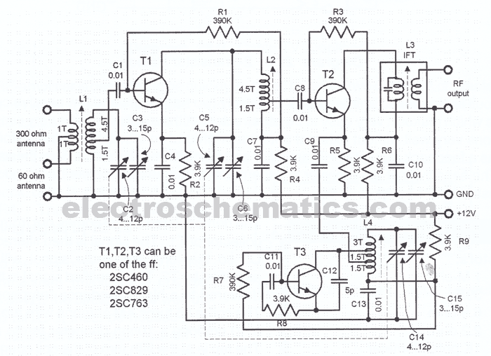
Car Analog tachometer circuit
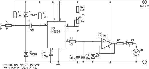
R1 = 1 kOhm
R2 = 1 MΩ
R3, R5 = 10 kOhm
R4 = 6.8 kOhm
R6 = see chart
P1 = 5 kOhm
P2 = see chart
C1, C2 = 100 nF
C3 = 220 nF
C4 = 47 µF
D1, D2 = 1N 4001
D3 = 4.7 V zener
IC1 = NE 555
IC2 = CA 3140
M1 = 100 µA meter, or 1 mA
The circuit operates by detecting the ignition pulses generated by the motor's breaker, which produces a rectangular waveform corresponding to the engine's firing frequency. The NE 555 timer (IC1) is configured in monostable mode, allowing it to react to each pulse and generate a corresponding output signal. This output signal is then processed by the CA 3140 operational amplifier (IC2), which converts the pulse frequency into a proportional voltage that drives the analog meter (M1).
The adjustable resistors P1 and P2 allow for calibration of the circuit to ensure accurate readings on the meter. P1 is used to set the characteristics of the output voltage based on the input frequency, while P2 is used to calibrate the meter to read full scale at 10,000 rpm. The use of capacitors (C1, C2, C3, and C4) in the circuit helps stabilize the voltage levels and filter out noise, ensuring a clean signal is delivered to the meter.
The diodes (D1, D2, and D3) serve protection and voltage regulation roles within the circuit. D1 and D2 are standard rectifier diodes that protect the circuit from reverse polarity, while D3, a zener diode, regulates voltage levels to prevent damage to sensitive components.
The circuit's design is suitable for installation in vehicles lacking a built-in tachometer, providing a reliable method to monitor engine speed. Proper installation and calibration are essential for achieving accurate readings, and the circuit can be adjusted to accommodate different engine types and configurations.This is a nice design for people who have no tachometer in the car or on the bike have. The circuit uses two ICs: an NE 555 and a CA 3140. The input of the circuit to the breaker of the motor (on the side that is not connected to ground). Thus, the ignition pulses within the circuit. By the two IC's, this signal then transformed into a speed-dependent voltage which is fed to the meter. The scale of the meter is 0 to 10 000 rpm. The circuit must be adjusted. For this, R6 IC2 temporarily disconnected. On R6 is a voltage of 4 V put. P2 is then adjusted so that the meter full scale deflection. Then again put R6. Then in mass and a voltage is alternating or block whose frequency is known (eg a transformer at 220 V). The speed to which the meter is set to be calculated using the formula: rpm = (30 * f * t) / n. This is the number of revolutions per minute rpm, f is the frequency of the alternating voltage, t is the number of motor cycles (eg 4-stroke) and n the number of cylinders.
This adjustment happens to P1. Remember always that the full scale is 10 000 rpm. R1 = 1 kOhm R2 = 1 M ½ R3, R5 = 10 kOhm R4 = 6.8 kOhm R6 = see chart P1 = 5 kOhm P2 = see chart C1, C2 = 100 nF C3 = 220 nF C4 = 47 uF D1, D2 = 1N 4001 D3 = 4.7 V zener IC1 = NE 555 IC2 = CA 3140 M1 = 100 uA meter, or 1 mA 🔗 External reference
Related Circuits
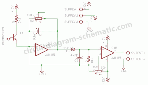
This circuit is a motion detection sensor that utilizes a light source and detector as an infrared motion detector. The motion sensor employs an infrared LED and a phototransistor. Since it relies on light, the sensor's sensitivity can be...
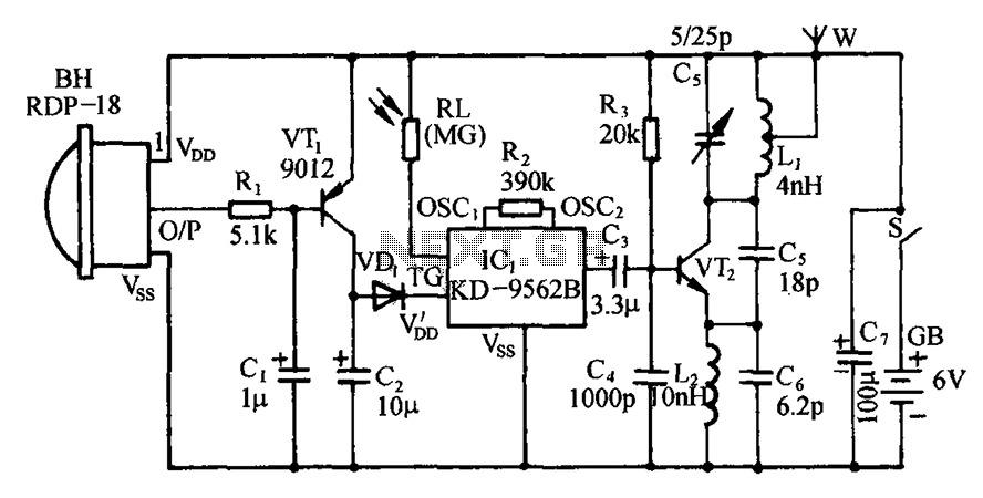
The circuit includes an infrared sensor head, electronic switches, an audible audio circuit, and an FM radio circuit. It is designed for installation in banks, treasuries, and other areas requiring supervision during evening hours in lieu of staff presence....
The LM35 from National Semiconductor is a precision centigrade temperature sensor that provides an analog output voltage. It operates within a temperature range of -55°C to +150°C and has an accuracy of ±0.5°C. The output voltage corresponds to 10mV...
This sensitive FM radio tuner is an ideal circuit for hobbyists who wish to construct their own tuners rather than purchasing a pre-assembled product. The FM radio tuner circuit is designed to receive frequency modulation signals, providing a clear and...
The circuit described is a discharge delay circuit that offers a longer delay compared to a standard rechargeable delay circuit, while also maintaining relatively high accuracy. The schematic diagram illustrates the input and output waveforms. Typically, when there is...
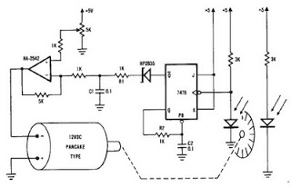
A simple encoder circuit for a DC motor can be constructed using the provided circuit diagram. The system includes the HA-2542 operational amplifier, a small 12 V DC motor, and a position encoder. During operation, the encoder generates a...
Warning: include(partials/cookie-banner.php): Failed to open stream: Permission denied in /var/www/html/nextgr/view-circuit.php on line 713
Warning: include(): Failed opening 'partials/cookie-banner.php' for inclusion (include_path='.:/usr/share/php') in /var/www/html/nextgr/view-circuit.php on line 713