
Anti-theft car audio system circuit diagram
The anti-theft car audio system circuit is designed to provide an effective security measure for vehicles by monitoring the integrity of the audio system wiring. The circuit operates on a 12V DC power supply sourced directly from the vehicle's battery, ensuring reliable operation.
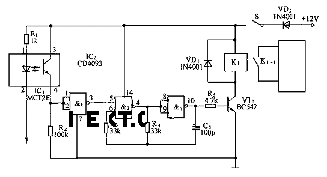
The circuit's operation begins with the closure of switch S1, which activates the optocoupler IC1. The internal light-emitting diode within the optocoupler illuminates, causing the phototransistor to conduct. This conduction results in a high output signal from IC1, which is fed into the first NAND gate. The output of this gate turns low, effectively signaling the second NAND gate, which is part of a low-frequency oscillator configuration involving NAND gates 2 and 3. While in this state, the circuit remains vigilant, ready to respond to any unauthorized tampering.
In the event that an intruder attempts to disable the audio system by cutting the audio cable, the interruption in the circuit causes the internal light-emitting diode of the optocoupler to cease operation. As a result, the output from IC1 drops to low, which in turn causes the first NAND gate to output a high signal. This change activates the low-frequency oscillator formed by NAND gates 2 and 3, producing an oscillation signal.
The oscillation signal is utilized to control transistor VT1, which acts as a switch for relay K1. When the relay is energized, its normally open contact K1-1 closes, completing a circuit that activates a beeper alarm. The alarm emits a loud sound, effectively alerting nearby individuals to the potential theft and deterring the intruder.
This circuit not only provides a straightforward method for monitoring the audio system but also incorporates essential components such as optocouplers and NAND gates to ensure reliable operation and quick response to unauthorized access. The design emphasizes simplicity and effectiveness, making it an ideal solution for enhancing vehicle security.Anti-theft car audio system circuit is shown, which is taken from the car battery 12V DC power supply. When after closing the switch S1. Optocoupler IC1 light emitting diode is lit, the internal light due phototransistor conduction, IC1 outputs a high level input to the NAND gate, the NAND gate 1 output low. The low increase in NAND gate 2 input feet, is controlled by a NAND gate 2, 3 consisting of NAND gate low frequency oscillator to stop, so that the entire circuit is in waiting alert state.
When the thieves cut the audio cable, since the optocoupler to the negative electrode inside the light-emitting diodes have been cut off at this time, so that IC1s feet vacant, internal light emitting diode immediately stop working, IC1 pin output low, NAND gate 1 output high, the NAND gate 2,3 consisting of a low frequency oscillator starts oscillation signal output control VT1 and intermittent relay K1: K1 normally open contact K1-1 also closed when closing time control a beeper alarm will sound a loud alarm will attract attention.
Related Circuits

This amplifying full-wave detector circuit is simple yet sensitive, featuring an almost zero rectification threshold. It provides a highly linear RF load to the final IF stage. The gain for the collector output is approximately given by r jre,...
Our programmable MP3 player has an interface to an LCD with a HD44780 controller. These are alphanumeric LCDs with one to 4 lines of text and 16 to 40 characters per line. However, these LCDs (and LCDs in general)...
The core component of this DIY metal detector circuit is the CS209A. The metal detector is constructed with a single coil of 100 µH. The CS209A contains an oscillator that forms an LC circuit; the inductance of the coil...
A 567 IC tone decoder/detector can be utilized to construct a remote control or intercom system. This circuit is capable of controlling a relay or transmitting an audio signal. The 567 IC is a versatile integrated circuit designed for tone...

The TDA7383 features a fully complementary PNP/NPN output configuration, enabling a rail-to-rail output voltage swing without the need for bootstrap capacitors. This design significantly reduces the component count, allowing for compact assemblies. An integrated clipping detector facilitates gain compression...

The simplest one-transistor audio mixer circuit diagram available. It utilizes a single transistor and can accommodate multiple audio signals, limited only by the user's budget. BC10. The one-transistor audio mixer circuit is a fundamental design that demonstrates the principles of...
Warning: include(partials/cookie-banner.php): Failed to open stream: Permission denied in /var/www/html/nextgr/view-circuit.php on line 713
Warning: include(): Failed opening 'partials/cookie-banner.php' for inclusion (include_path='.:/usr/share/php') in /var/www/html/nextgr/view-circuit.php on line 713