
One Transistor Audio Mixer

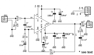
The one-transistor audio mixer circuit is a fundamental design that demonstrates the principles of audio signal mixing using minimal components. The core of the circuit is a single transistor, which acts as the main amplifying element. This transistor is typically a BC10, known for its suitability in low-power audio applications.
The circuit allows for the mixing of multiple audio inputs, such as microphones or musical instruments. The audio signals are fed into the base of the transistor through coupling capacitors, which block any DC component and allow only the AC audio signals to pass. This configuration ensures that the audio signals can be superimposed without interference from any DC biasing.
The transistor operates in its active region, where it amplifies the combined audio signals. The output is taken from the collector of the transistor, which can be connected to a speaker or further audio processing equipment. The gain of the circuit can be adjusted by varying the resistor values in the emitter and collector circuits, allowing for flexibility in audio output levels.
Power supply requirements for this circuit are minimal, typically operating at low voltages, which makes it suitable for battery-powered applications. The simplicity of this design, combined with the potential for expansion by adding more audio inputs, makes it an excellent choice for basic audio mixing tasks in various electronic projects.The simplest one transistor audio mixer circuit diagram on the net. It has only one transistor and can support as many audio signal as you can afford. BC10.. 🔗 External reference
Related Circuits
A new user has joined the forum and is seeking assistance with circuit design. They express a desire for guidance and acknowledge their inexperience in the subject. In circuit design, it is crucial to understand the fundamental components and their...
The interval between rings can be adjusted by changing the value of the 1 Meg resistor. A 70 volt, 30 Hz ringing voltage is generated from the 120 volt side of a small 12.6 VAC power transformer (Radio Shack...
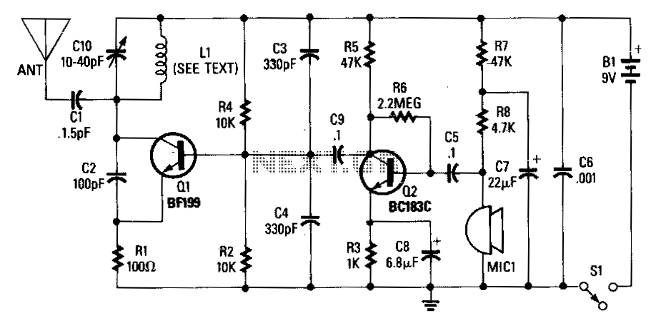
An adjustable capacitor C10 and a coil L1 create a tank circuit that, along with Q1, C2, and R1, oscillates at a frequency within the FM band. The center frequency is adjustable by tuning C10. An electret microphone, M1,...
One of the more frequently requested projects on HeadWize has been a switchbox for selecting multiple audio inputs. I built this passive preamp/switchbox several years ago to switch between two stereo sources (a portable FM tuner and portable CD...
The second-order multipurpose filter described here can function as a low-pass, bandpass, high-pass, or notch filter at audio frequencies. Its unique feature is the ability to independently vary all characteristics using potentiometers. In basic filters, only one k value...
The following circuit illustrates a UHF Indicator Wavemeter Circuit Diagram. This circuit utilizes dual BF494 transistors. Features: the oscillator is... The UHF Indicator Wavemeter Circuit is designed to measure and indicate the frequency of ultra-high frequency (UHF) signals. The circuit...