
APM2.0 5V/Vcc Schematic
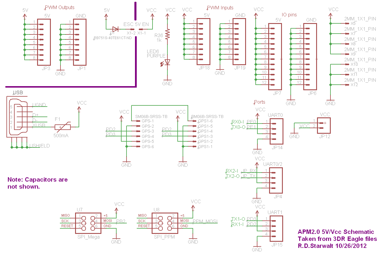
The APM2.0 circuit features a PWM output section strategically positioned in the upper left corner of the schematic, clearly marked by a heavy purple line. This section is bridged by jumper JP1, which plays a crucial role in the functionality of the circuit. The inclusion of diode D1 is significant, as it facilitates the flow of current through JP1 while simultaneously introducing a voltage drop. The remaining voltage after this drop is labeled as Vcc, which serves as the primary power supply for the circuit.
Components situated outside the delineated purple corner are powered by Vcc, establishing a clear distinction between the power distribution within the circuit. This design is particularly advantageous as it allows the APM2.0 to be powered through USB connections. When connected to a computer or USB hub, the USB port supplies power directly to the APM2.0, ensuring its operation.
Furthermore, the presence of a fuse on the APM2.0 side of the USB connector serves as a protective measure, safeguarding the circuit from potential overcurrent situations. It is essential to note that any 5V source connected to the specified Vcc/5V points outside the purple corner, along with a common ground, can effectively power the APM2.0. This versatility in power sourcing enhances the circuit's functionality and adaptability in various applications.Note that I have separated the PWM Output section into the upper left corner with a heavy purple line that is bridged by the jumper JP1 on the APM2. 0. This is to emphasize that diode D1 passes current through JP1 (and drops voltage). The remaining energy is then called `Vcc`. Everything outside the purple corner is Vcc. This is why the USB will po wer the APM2. 0 when connected to a computer/USB hub. Note the fuse on the APM2. 0 side of the USB connector. In fact, any 5V source connected to any of the indicated Vcc/5V points outside the purple corner (with GND of course) will power the APM2. 0. 🔗 External reference
Related Circuits
This audio amplifier design utilizes two LM3886 chips per channel in a parallel configuration, based on the PA100 parallel amplifier detailed in National Semiconductor's application note AN1192. The amplifier can deliver approximately 50W into an 8-ohm speaker and 100W...
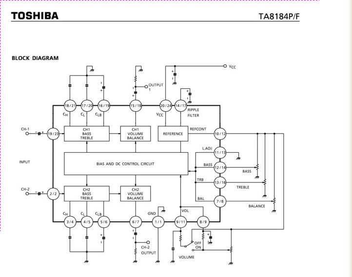
The TA8184P and TA8184F are DC-controlled integrated circuits designed for dual volume, balance, and tone (bass and treble) control. These ICs are suitable for applications in car stereos, radio cassette players, music centers, and TV multiplex sound receivers, providing...
The objective is to enhance information transmission by utilizing articles. Please contact us via email at [email protected] within 15 days if there are issues related to article content, copyright, or other concerns. Prompt action will be taken to resolve...
The LM4992 stereo audio power amplifier can be utilized to design a straightforward audio power amplifier project suitable for portable electronic devices. This amplifier circuit is capable of delivering 1 watt of continuous average power per channel to an...
This circuit is designed for children's entertainment and can be installed on bicycles, battery-powered cars, motorcycles, as well as models and various games and toys. When switch SW1 is positioned as indicated in the circuit diagram, it generates the...
This circuit is designed to provide alerts after a predetermined time interval. It is ideal for tabletop games that necessitate a fixed duration for answering questions or moving pieces. In this context, it serves as a contemporary alternative to...