
APPLIANCE TIMER

This circuit design employs a robust two-stage counter mechanism to facilitate precise timing intervals. The thumb wheel switches S1 and S2 allow users to set the desired time duration, with the circuit capable of counting up to 3600 seconds (1 hour) in 1-second increments. The core timing functionality is established through the integration of a 60-Hz AC power line signal, which is processed by the divide-by-60 counter configuration of component A1. This component effectively divides the incoming frequency to generate a stable 1-Hz signal, which serves as the timing pulse for the subsequent stages of the circuit.
The output from A1 is fed into A2, which further processes the signal and activates A3. Each of these stages can be programmed to perform specific tasks, enhancing the versatility of the timer. The activation of the timing cycle is initiated when switch S3 is closed, causing the R4 bus to transition to a low state. This action triggers the timing mechanism, allowing the circuit to commence its countdown operation.
A4 functions as a relay driver, controlling relay K1, which is critical for managing the application of AC power to the device being timed. When the timing cycle is active, K1 remains closed, ensuring that power is supplied continuously to the load. Additionally, an LED indicator is integrated into the design to provide a visual cue that the timing cycle is in progress, enhancing user interaction and feedback.
Overall, this circuit is ideal for various applications, including kitchen timers for cooking and darkroom timers for photography, where precise timing is essential. The design's reliance on common components and straightforward logic makes it accessible for implementation in various electronic projects.Controls intervals up to 1 h in 1-s increments as programmed by thumb wheel switches S1 and S2. Circuit is basically two-stage programmed counter driven by 1-s clock derived from 60-Hz power line. A1 is connected as divide-by-60 counter triggered by 60-Hz signal developed across D2. 1-Hz output from A1 triggers A2 which in tum triggers A3, all pro grammable timers. When S3 is closed, R4 bus goes low to start timing cycle. Relay driver A4 holds relay K1 closed for application of AC power to device being controlled and energizing of LED to indicate active timing cycle. Applications include uses as kitchen and darkroom timers, -W. G. Jung, "IC Timer Cookbook, " Howard W. Sams, Indianapolis, IN, 1977, p 214-218. 🔗 External reference
Related Circuits
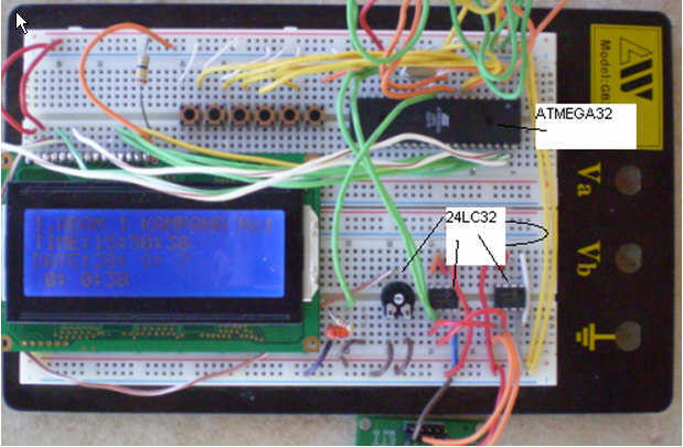
This circuit is a church bell controller. Basic component is an ATmega32 microcontroller. At the circuit 2 24LC32 EEPROM memories is being used, the 1st for internal standard melodies and the 2nd one is for user's compositions. This feature...
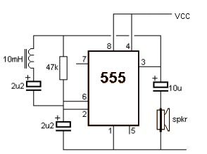
A simple metal detector circuit can be implemented using a 555 timer chip. The schematic diagram illustrates that this project requires only a few external electronic components. The metal detector circuit utilizing a 555 timer operates in astable mode, generating...
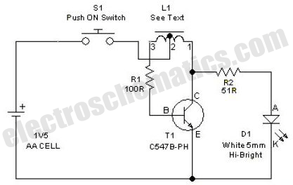
This simple LED driver circuit allows the operation of up to seven LEDs using a single NiMH (Nickel Metal Hydride) AA cell. The circuit generates voltage pulses. The LED driver circuit is designed to efficiently power multiple LEDs while maintaining...
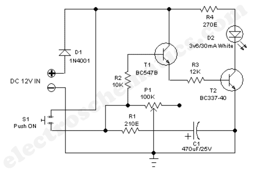
The 555 adjustable timer circuit initiates timing upon activation. A green LED illuminates to indicate that the timing process is underway. Once the designated time period concludes, the... The 555 timer IC is a versatile device widely used in various...
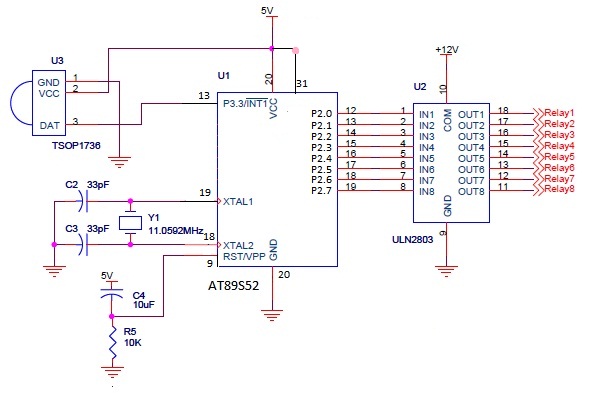
The infrared (IR) circuit is designed to control multiple devices using a TV remote. Unlike standard circuits that can typically switch only one device, this circuit allows for the operation of different devices with the same remote by utilizing...
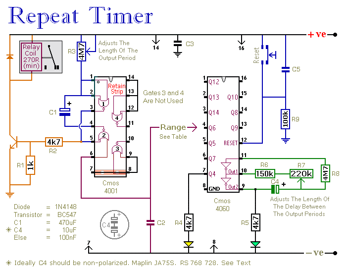
This circuit features an adjustable output timer that can re-trigger at regular intervals. The output duration can range from a fraction of a second to over half an hour, with the ability to recur at intervals from seconds to...